26 27
EN – Installation and operation guide SIMPLE MOVE 102
EN – Installation and operation guide SIMPLE MOVE 102
EN
EN
2 STARTUP AND STANDARD USE
2.1 Switching the installation on 2.3 Standby / reactivation of the electronic control system
2. If the indicator light remains unlit or the
number of fl ashes is diff erent than expected:
see diagnostics on page 43.
1. The indicator fl ashes (twice).
The power supply of the drive is ON
and waiting for self-learning.
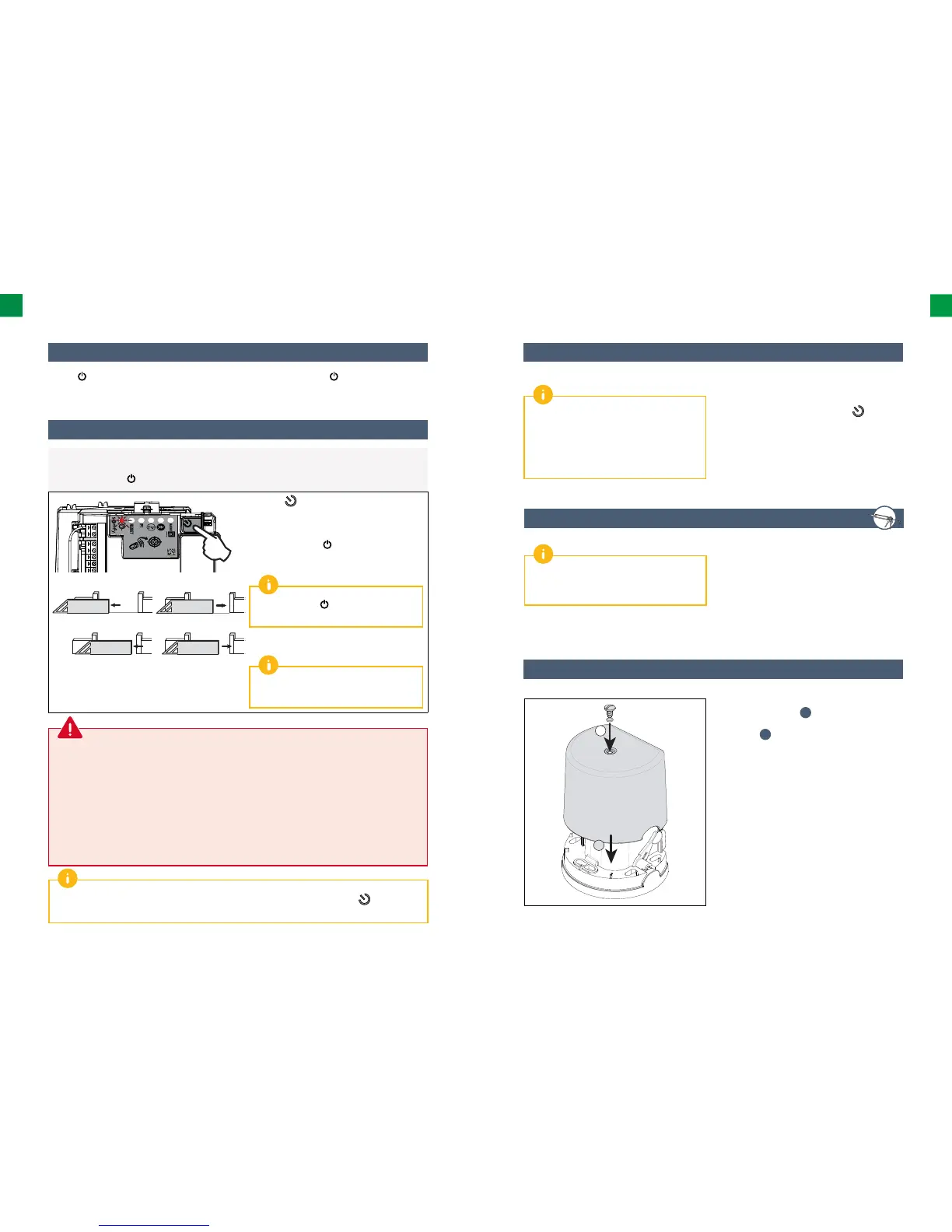
2.2 Gate track self-learning
Preliminary requirements – before starting self-learning, check whether:
• The installation is switched on:
the indicator light
fl ashes (twice).
• The gate is at its mid-point.
• The drive is locked.
Press the button on the electronic control
system.
• The gate opens, closes, opens partially and
closes again.
• The indicator light emits a continuous light.
Self-learning has been successfully
completed and the drive is operational.
If the indicator light
fl ashes (twice), begin
the self-learning process again.
The gate must be closed once self-learning
is complete.
If the gate is open, see the IMPORTANT box
below.
During the self-learning process, pressing button 1 on the remote control or the button on the
electronic control system stops the gate and the self-learning process.
IMPORTANT:
If the gate is open once self-learning is complete:
1. Delete the settings (see page 42).
2. Switch the drive off .
3. Replace the cables connected to terminals 9 and 10 (green label M1) of the electronic control
system (see “Drive wiring”, page 12).
4. Unlock the drive.
5. Position the gate at its mid-point.
6. Lock the drive.
7. Switch the drive on.
8. Start the self-learning process again.
2.4 Plugging the holes
To check whether the drive is switched on or to
check/modify the settings, press the
, button
for 2 seconds to reactivate the electronic module.
Once all the cables are laid, plug all the holes
(oblong holes, cable feed holes) using silicone.
Once the self-learning process is complete,
the electronic module automatically switches
to standby aſt er 5 minutes of inactivity to save
energy.
In standby mode, all the indicator lights are off .
You are strongly advised to plug all the holes to
avoid short circuits caused by insects.
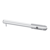
2.5 Shield assembly
2
1
1. Place the shield on the drive fl ange (base).
2. Mount the gasket
j
, to ensure the tight
fi tting of the drive unit and then the shield
screw
i
.
3. Tighten the shield.