14 15
EN – Installation and operation guide SIMPLE MOVE 102
EN – Installation and operation guide SIMPLE MOVE 102
EN
EN
Preliminary requirements for assembly
▶
Stops on the ground
▶
Gate inspection
▶
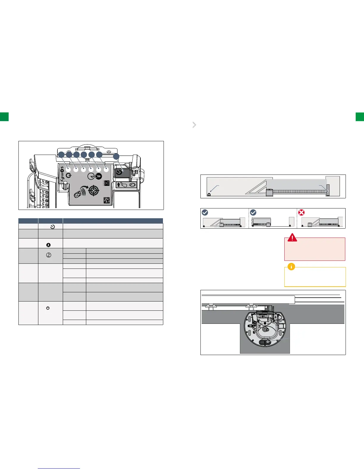
Presentation of the electronic control system
▶
Positioning the drive
▶
Preliminary electrical system
The gate movement track must be limited by stops fi rmly fi xed to the ground. The
stops limit its extreme position during opening while the post performs this function during closing.
• The gate must be in good technical condition, free from mechanical damage.
• The gate must be in a horizontal position during the whole movement cycle and it must open and close
without the necessity of using excessive power. Check whether the gate is perpendicular to the ground and
whether there are no obstructions that could prevent proper gate movement.
Closing stop
Opening stop
Gate
Concrete
foundations
Laying of cables
Required cables
• Mains supply: 3 x 1.5 mm 2 or 3 x 2.5 mm
2
conductor
for outdoor use (type H07RN-F minimum)
• Photocell connection: 2 x 0.75 mm
2
conductor
• Other accessories: see page 16
The supply cable must be laid in
accordance with the electrical standards
in force in the country of use.
If the cables cannot be laid underground,
use a cable grommet which will withstand
the weight of vehicles.
Laying cables
• The cables laid underground must be equipped with a protective
sheath with a suffi cient diameter to contain all the cables.
• Connect the power supply of 230 V as close to the location of the
drive unit assembly as possible.
30s
R
A
DIO
G F E D C B
A
Mark Name Function
A
Button
Self-teaching launch Electronic control system launch
B Indicator light
RADIO
Lights up each time the electronic control system receives
a command via radio
C Indicator
light
Lights up during activation/deactivation of the opening
for pedestrian entry
D Indicator
light
On automatic closing of the gate is activated
Off automatic closing of the gate is not activated
Flashing the “automatic closing” setting is selected
E Indicator
light P1
Off the gate operates at standard speed
Slowly
fl ashing
the gate operates at low speed
Flashing the gate “speed” setting is selected
F Indicator light
RESET
On only settings or the settings and the radio control
points are deleted
Flashing the settings and radio control points deletion
function is selected
G Indicator
light
On the drive unit is functioning correctly – the electronic
control system is reactivated
Off the drive unit is functioning correctly – the electronic
control system is on standby
Flashing see diagnostics page 32