7.11
FINAL DRIVE
7
Installation
1. Install new spring ring on drive shaft. Apply an anti-seize
compound to splines. Align splines of drive shaft with
front gearcase and install by lightly tapping on drive shaft
with rubber faced hammer.
2. Install drive shaft in strut.
3. Install the lower A-arm onto the lower ball joint, torque nut
to 25 ft. lbs. (35 Nm) and install new cotter pin.
4. Install hub and tighten spindle nut to 70 ft. lbs. (95 Nm).
FRONT PROPSHAFT REMOVAL
1. Elevate front end and safely support machine under
footrest / frame area.
2. Remove wheel nuts and wheel.
3. Remove cotter pin and nut from lower A-arm ball joint.
Remove lower A-arm from ball joint. (See below)
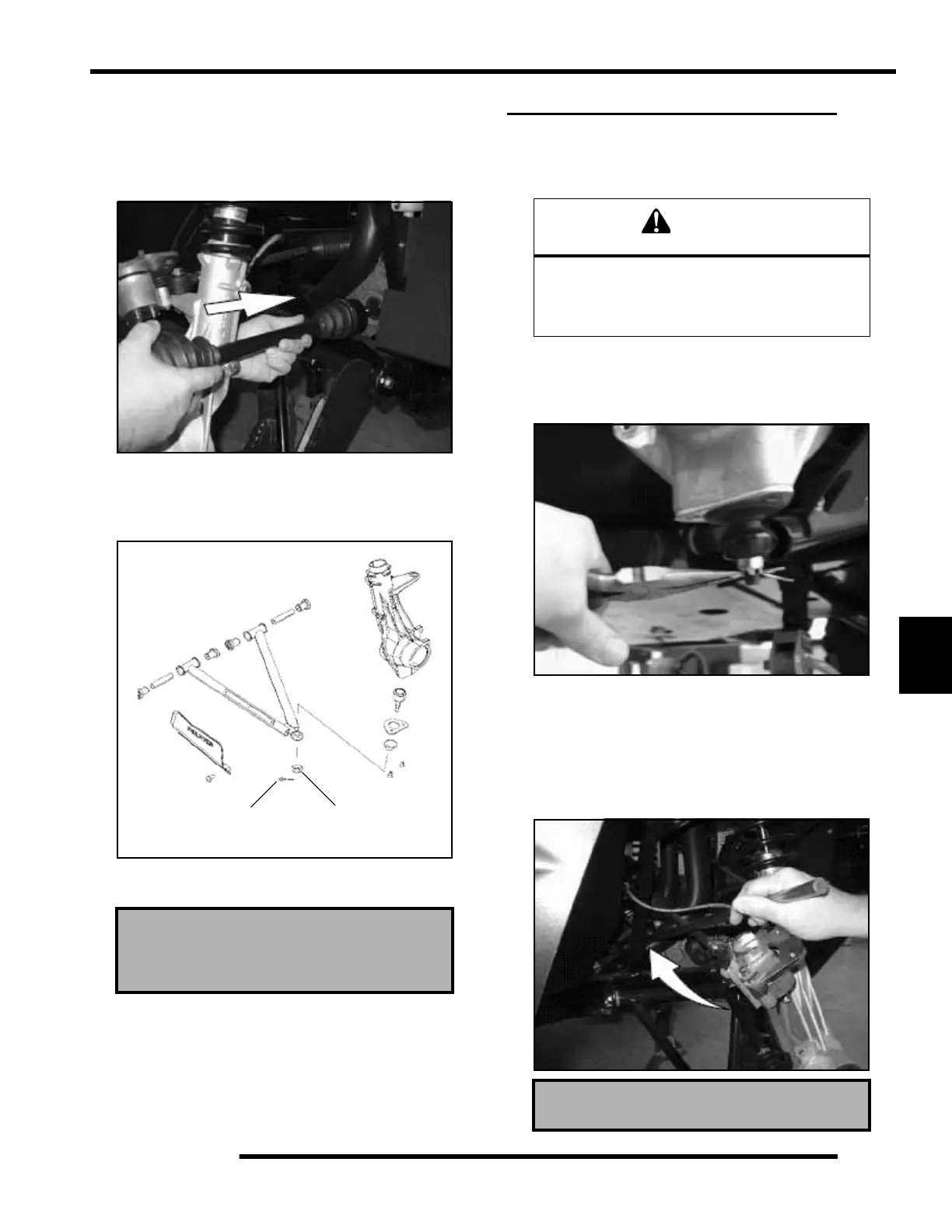
4. Use the Roll Pin Removal Tool (PN 2872608), to remove
the roll pin from prop shaft at the front housing. Slide prop
shaft back and away from front housing. Pull sharply
forward to remove from transmission shaft.
NOTE: The roll pin can also be accessed through
the hole in the skid plate shown in the photo below.
Front Spindle Nut Torque
70 ft. lbs. (95 Nm)
25 ft. lbs.
(35 Nm)
Cotter Pin
CAUTION
Serious injury may result if machine tips or falls.
Be sure machine is secure before beginning this
service procedure. Wear eye protection when
removing bearings and seals.
Roll Pin Removal Tool (PN 2872608)
 Loading...