10.5
ELECTRICAL
10
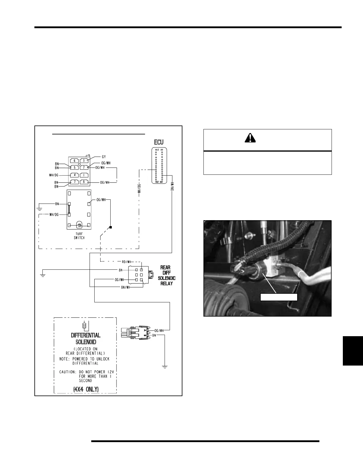
Differential Solenoid Circuit Operation
When the switch is pushed to activate “Turf” mode, the White/
Green wire is connected to ground via the Brown wire at the
AWD / Diff-Lock Switch and signals the ECU to energize the
Rear Diff Solenoid Relay.
Depending on vehicle speed and gear position criteria, the
ground path is then sent from the ECU to the Rear Diff
Solenoid Relay. This activates the solenoid and sends 12 volt
“Key On” power from the RD/WH wire to the OR/WH wire of
the Differential Solenoid.
If the rear carrier fails to switch from operational modes:
• Check the connector located under the left rear fender.
Look for loose wires or bad connections.
• Check for power from the connector, to ensure the
solenoid has power to be activated.
• Check the operator’s switch wires for loose
connections.
• Remove solenoid from carrier and ensure the solenoid
plunger is actuating.
Brake Light Switch
1. The brake light switch is located near the steering gearbox
along the frame. The brake pressure switch is installed into
this block.
2. Disconnect wire harness from switch.
3. Connect an ohmmeter across switch contacts. Reading
should be infinite (•).
4. Apply foot brake and check for continuity between switch
contacts. If there is no continuity or greater than .5 ohms
resistance when the brake is applied with slight pressure,
first clean the switch contacts and re-test. Replace switch
if necessary.
Rear Differential Solenoid Circuit
AWD / Diff-Lock
Switch
Key-On
Power
CAUTION
Do not power the solenoid with 12 Volts for more
than 1 second, or damage may occur
to the solenoid.
Brake Switch
 Loading...