3.58
9850043 R01 - 2017-2021 RANGER 500 / 570 Service Manual
© Copyright Polaris Inc.
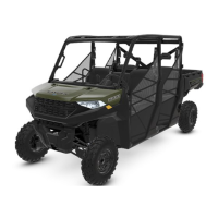
3. Measure connecting rod small end ID. Inspect
bearing surface for damage.
Piston Pin Degree of Fit:
Pin should be a push-fit by hand with piston at room
temperature or warmed slightly
Connecting Rod Small End ID:
Std.: 0.8665 - 0.8670″ (22.010 - 22.023 mm)
4. Measure piston ring to groove clearance by placing
the ring in the ring land and measuring with a
thickness gauge. Replace piston and rings if ring-to-
groove clearance exceeds service limits.
Piston Ring-to-Groove Clearance
Top Ring:
Std.: 0.0011 - 0.0037" (0.030 - 0.095 mm)
Service Limit: 0.0042" (0.108 mm)
Second Ring:
Std.: 0.0007 - 0.0029" (.020 - 0.076 mm)
Service Limit: 0.0035" (0.89 mm)
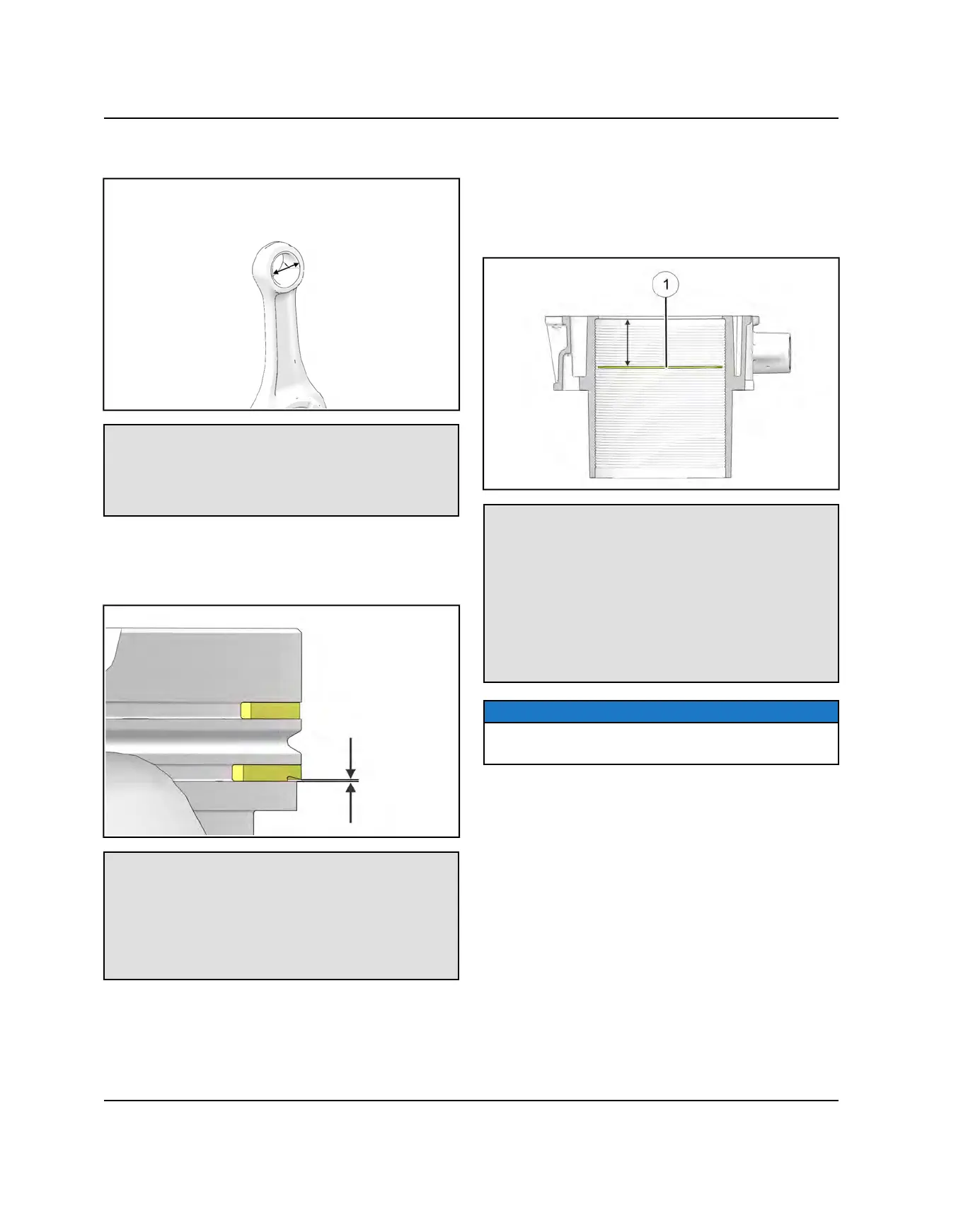
PISTON RING INSTALLED GAP
1. Place each piston ring inside cylinder. Use a piston to
push the ring squarely into place 1” (25.4 mm) down
from the cylinder head gasket surface.
2. Measure installed gap with a feeler gauge at location
q
.
Piston Ring Installed Gap
Top Ring:
Std: 0.0059 - 0.0122" (0.15 - 0.31 mm)
Limit: 0.0137" (0.35 mm)
Second Ring:
Std: 0.0094 - 0.0196" (0.24 - 0.50 mm)
Limit: 0.022" (0.56 mm)
Oil Ring Rails:
Std: 0.0098” - 0.0401" (0.25 - 1.02 mm)
Limit: 0.0480" (1.22 mm)
NOTICE
Always check piston ring installed gap after re-boring a
cylinder or when installing new rings.
ENGINE / COOLING SYSTEM
 Loading...