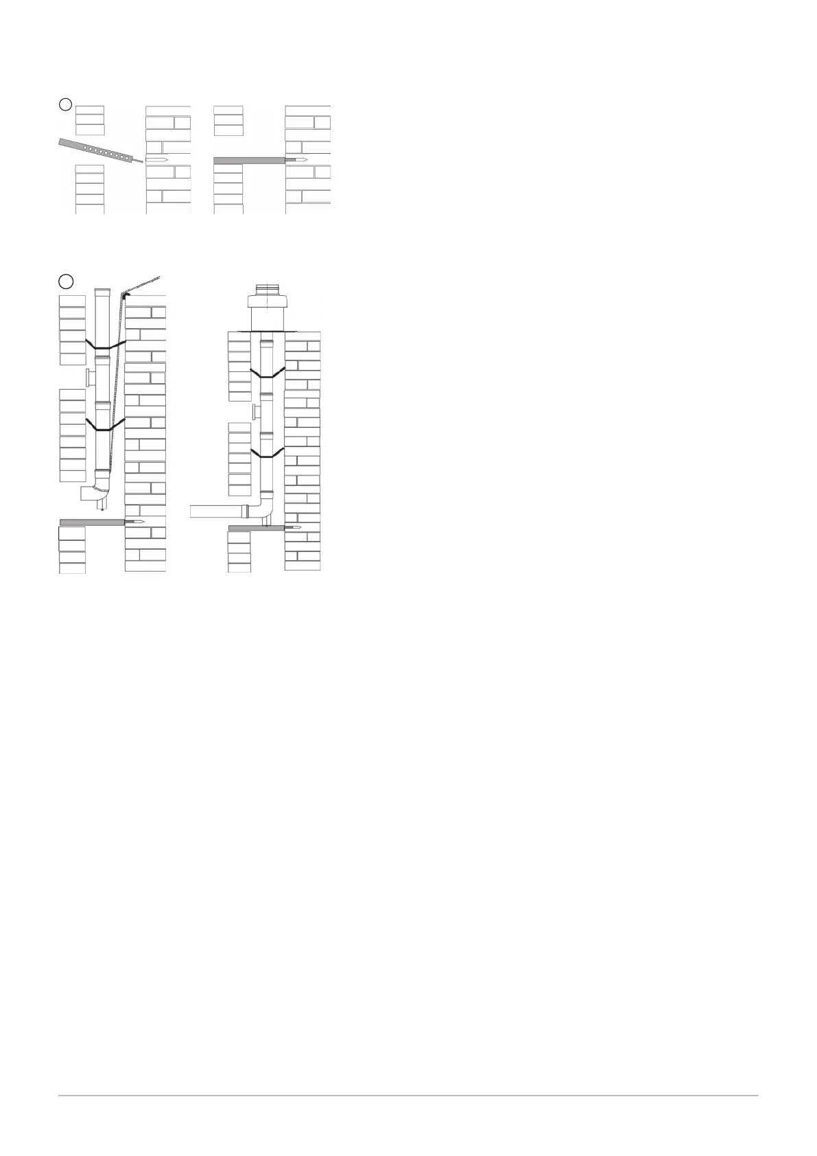
2. For fastening the support rail in the opposite wall of the shaft opening,
a bore hole (Ø=10 mm) must be provided on the level fo the opening
edge. Then the pin of the support rail has to be hammered into the
bore hole.
3.
The flue pipe is lowered from the top into the shaft. For this, connect a
rope to the support leg and insert the pipes, section by section, from
the top. To prevent the components sliding apart during assembly, the
rope must be kept on tension until the final assembly of the flue pipe.
If spacers are necessary, these have to be fitted to the duct at least
every 2 m.
4. Cant the spacers at a right angle and align centric in the shaft. Pipes
and formed parts are to be installed in such a way that the connectors
are arranged counter to the flow direction of the condensed water.
After the pipes have been inserted, place the support leg in the support rail
and align (flush and without tension). The shaft cover at the chimney head
must be assembled in such a way that no rainfall can get into the space
between flue pipe and shaft and the air for back ventilation can flow freely.
Fig.14
Fig.15
6 Installation
44 Paramount five 30 – 115 7703046 - 01 - 23072018