Tab.8 Dimensions and connections
Model Paramount
50/60
Paramount
80
Paramount
95
Para‐
mount 115
Heating flow
G 1
1
/
2
" G 1
1
/
2
" G 1
1
/
2
" G 1
1
/
2
"
Heating return
G 1
1
/
2
" G 1
1
/
2
" G 1
1
/
2
" G 1
1
/
2
"
Gas connection G 1" G 1" G 1" G 1"
Safety valve G 3/4" G 3/4" G 3/4" G 3/4"
Condensate connection Ø 25 mm Ø 25 mm Ø 25 mm Ø 25 mm
Dimension A [mm] 447 542 580 580
Dimension B [mm] 168 168 163 163
Dimension C [mm] 132 132 152 152
3.5
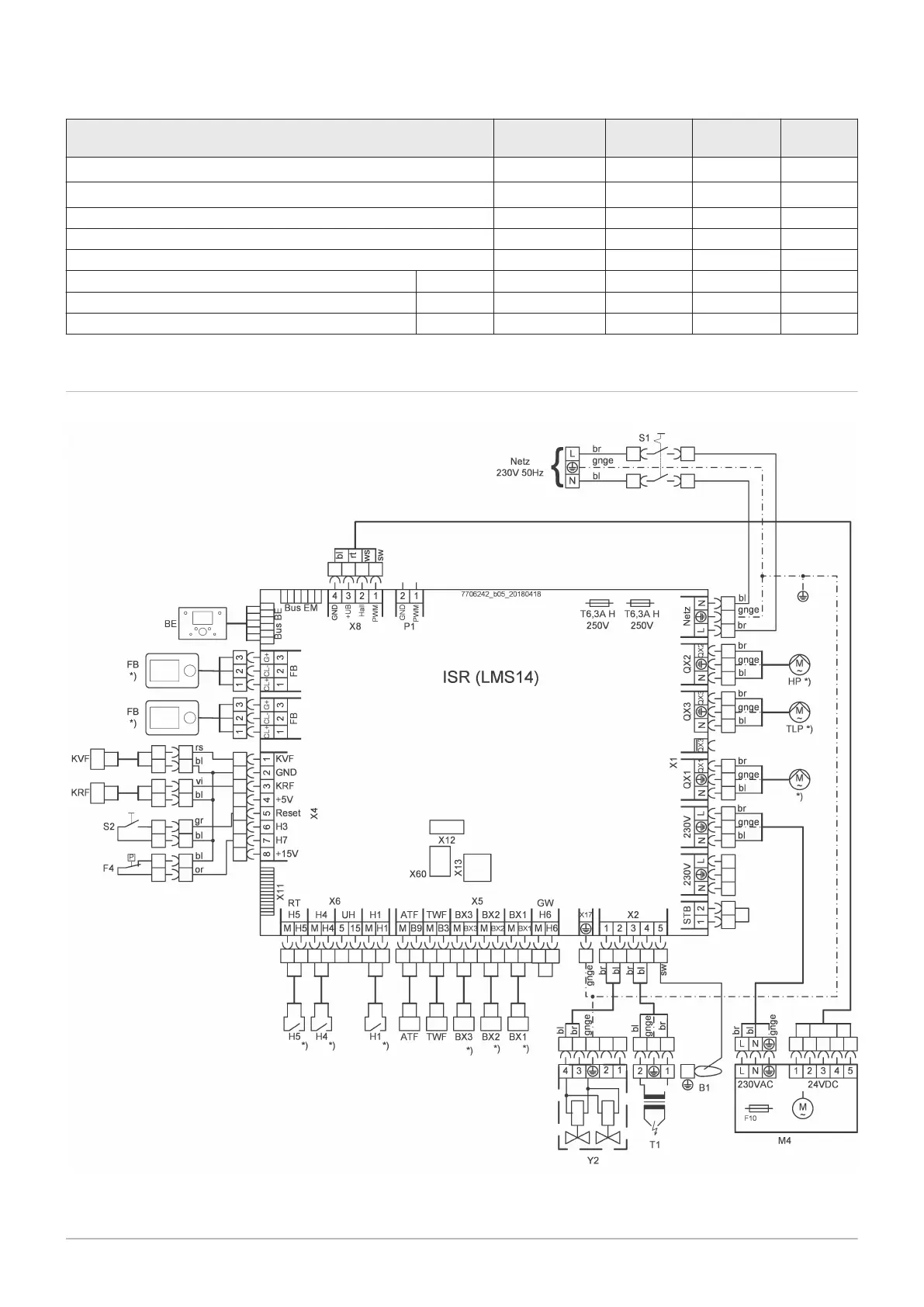
Wiring diagram
Fig.4
Wiring diagram Paramount 30 / 40
ATF Outdoor temperature sensor QAC 34
B1 Ionisation electrode
BE Operating unit
BusBE Bus connection for operating unit
3 Technical specifications
7703046 - 01 - 23072018 Paramount five 30 – 115 21