0700_GB-tRANs-PENDELRAD_983
GB
FEELEr wHEEL
- 24 -
Transport-Feeler wheel
Tyres
SERVO 45, SERVO 55 SERVO 35
10.0/75-12 10 PR 23x10,50-12 6 PR
Max. 5,5 bar pressure. Max. 2 bar pressure.
As feeler wheel
• Fix the depth
1. Spindle (1) adjusment
2. Spindle (1) adjusment
As transport wheel
• Doing this relieves the
tractor’s rear axle and lifting gear.
Very important remark:
When transporting, the upper link (1) must only be
pinned in the slot with the plough
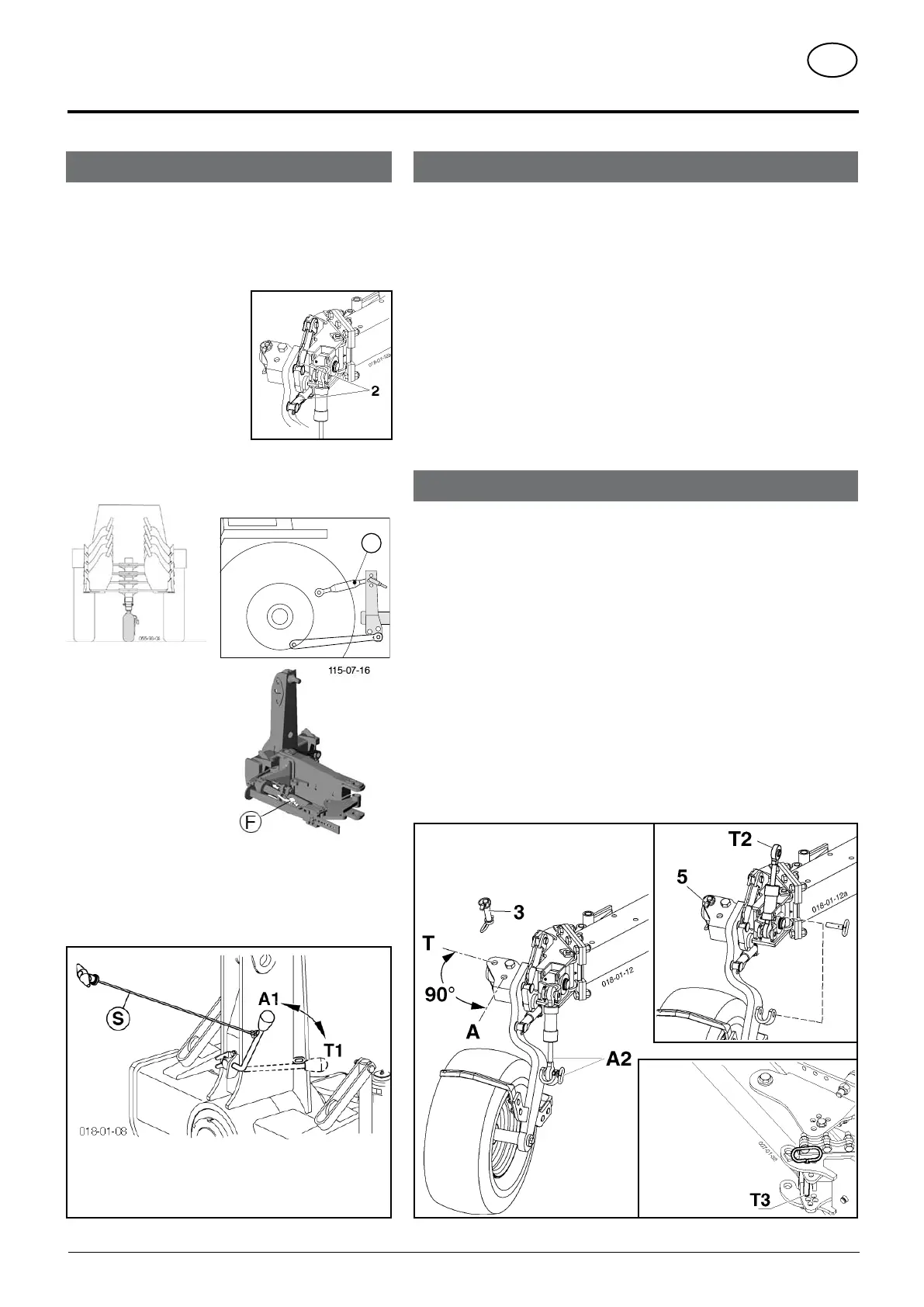
A1 = working position
T1 = transport position
Changing to working position
- SERVO PLUS only: Open hydraulic valve (F)
- Raise plough using tractor’s lifting gear
- Release locks (for safety reasons do this from the tractor seat with the rope
(S)
With that swivel the control lever 90° (position A1).
- The turning unit positions the plough vertically.
- Remove bolts (3), swivel the support wheel console about 90° into working
position and pin with the bolts (3) again (A).
Secure bolts with linch pin (5).
- Cutting width adjustment :
- for the servo plus : hydraulically
- for the standard plough : put the axle T3 in the position you want.
- Cylinder in working position (A2)
Changing to transport position
- Adjust the plough in the smallest cutting width
- for the servo plus : hydraulically
- for the standard plough : put the axle T3 in the position you want.
- Cylinder in transport position (T2)
pin with the bolts
-
Remove bolts (3), swivel the support wheel console about 90° into the transport
position and pin with the bolts (3) again (T).
Secure bolts with linch pin (5).
- Release locks.
With that swivel the control lever (on the attaching frame) 90° (position T1).
- Lift the plough with the tractor’s lifting gear.
- The turning unit slowly positions the plough horizontally until locking bolts on
the attaching frame automatically engage.
-
SERVO PLUS only: Close hydraulic valve (F)
A, A2 = working position
T, T2 = transport position
Transport position
SERVO Standard



 To Next Page