- 26 -
GB
0700_GB-VoRGEzoGENEs-tRANs-PENDELRAD_983
FEELEr wHEEL
6. Activate transport safeguard on attaching frame
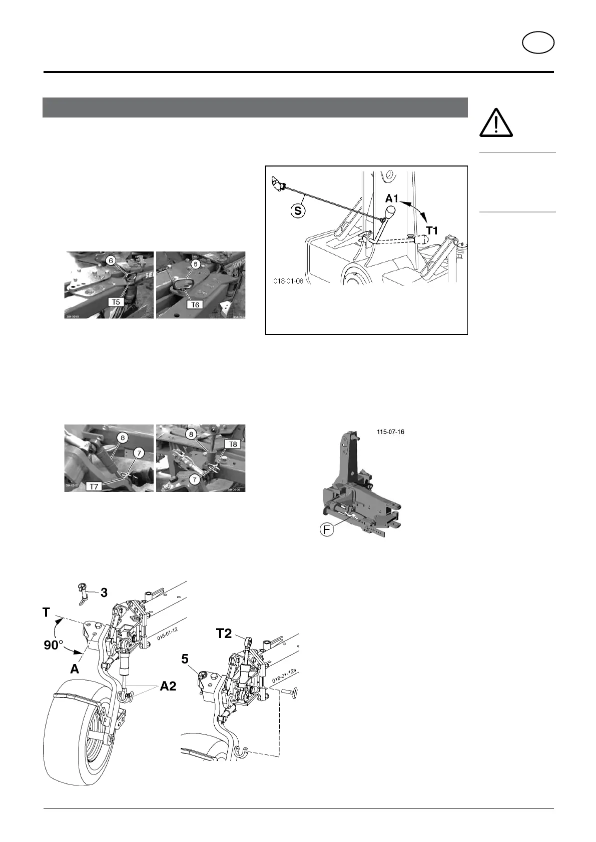
- With that swivel the control lever (on the attaching
frame) 90° (position T1).
7. Lift the plough with the tractor’s lifting gear.
- The turning unit slowly positions the plough
horizontally (transport position) until locking bolts
on the attaching frame automatically engage.
8.
SERVO PLUS only: Close hydraulic valve (F)
A1 = working position
T1 = transport position
1. Adjust the plough in the smallest cutting width
- via hydraulic cutting width adjustment with SERVO
PLUS plough
- via swivel cylinder on plough with hydraulic frame
swing-in
2. Lower plough and possibly hydraulic wheel to the
ground
3. Bring wheel console into transport position.
- Move pin (6) from “pos. T5” to “pos. T6” and
insert
(when equipped with hydraulic frame swing-in, close
stop valve when cylinder is fully extended)
4. Bring cylinder or damper into transport position
- Remove pin (7)
- Swivel damping cylinder (8) from “pos. T7” to “pos.
T8”
- Insert pin (7) and secure
5. Swivel wheel support into transport position
- remove bolts (3)
- swivel the support wheel console about 90°
- pin with the bolts (3) again (T)
- secure bolts with linch pin (5)
A, A2 = working position
T, T2 = transport position
Changing to transport position
Safety warning!
Make sure that
swivel area is free
and that nobody
is standing in the
danger area.




 To Next Page