(983) ANBAu 0600-GB
GB
aTTaCHing TO THE TraCTOr
- 8 -
Attaching to the tractor
Safety advice:
See supplement A1, Pt. 8a-h
- Switch tractor’s hydraulics to control position.
- Attach implement to lower link and secure with linch pin.
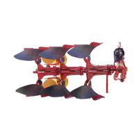
Note
The attaching frame can be positioned horizontally by turning
the tilt spindle (11).
Doing this enables an easier coupling to the lower link.
Then turn the tilt spindle (11) back. See chapter „OPERATION“
also.
Pin upper link (1)
- Pin upper link (1) so that the attachment point (P1) on the plough
during operation is somewhat higher than the attachment point
(P2) on the tractor.
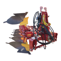
Securing lower link
If the tractor’s hydraulic control
is to be steered over the lower
link, then the upper link should
be positioned in the slot (LL) on
the attaching frame.
Securing upper link
If the tractor’s hydraulic control is to be triggered over the upper
link, then both the (RL) borings on the attaching frame are to be
used.
- Couple hydraulic hoses to the tractor.
Important advice:
Supportstand in the working position
1. Lock the bolt (1) into the hole of the stand plate.
2. Secure the supportstand with linch pin (K).
Insert pin only in the first hole.
• Do not use holes in
pos. 2 - 9
- otherwise support stand will be damaged when turning plough
Lighting and Warning equipment
When travelling in fog, half-light or at night,
protruding parts are to be clearly indicated.
Advice on the application of warning signs,
reflective film or paint and lighting units can
be found in the instructions for ancillary equipment in supplement C.
PôTTINGER can supply lighting units and warning signs upon
request.
Always observe the statutory regulations.
Removal from tractor
Hint: The shear points are hardened so when set down onto hard surface
(stone, concrete, etc.), risk of breaking exists. Therefore lower the shear
points onto a suitable support (wooden board)!
- Turn plough frame to working position and park the implement on stable
and even ground
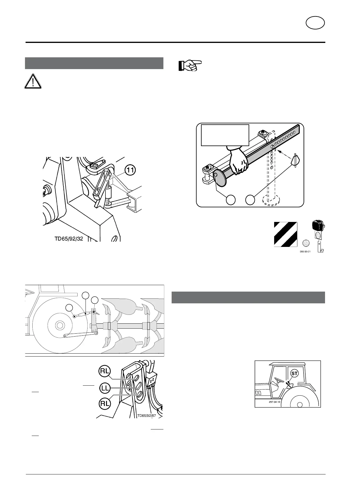
- Move the control lever (ST) back and forth several times to reduce
pressure in the hydraulic lines.
- Switch tractor’s hydraulics to control
position.
- Disconnect hydraulic hoses from
tractor.
- Swing support stand down and
secure with pins.
- Detach upper and lower links from
implement.
Garaging, cleaning and winter storage of the implement
• Observe the points in the chapter „MAINTENANCE AND SERVICE“!
495.694
Arbeitsposition
Working position
Position travail
1
2