7
Equipment Description
Powered by Safety
®
01.4IB.48070A
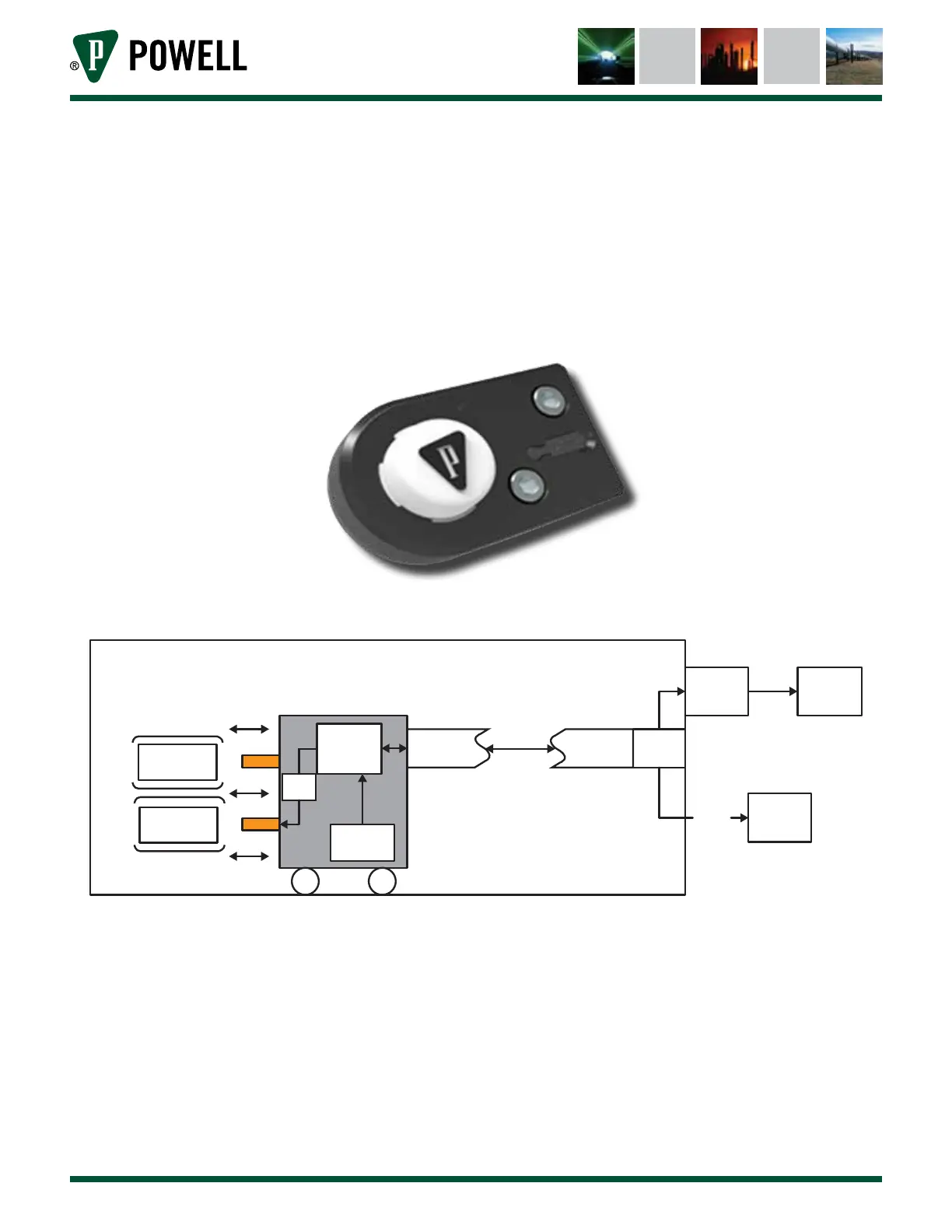
3) External Indication Module (EIM)
The EIM (Figure 3) is connected to the IRIM via RJ-45 connection and has an isolated USB
connection for use by a laptop along with three LEDs behind a white lens for displaying circuit
breaker condition. LED colors are GREEN (slow pulse - satisfactory condition), AMBER (slow pulse
- warning), and RED (slow pulse - alarm). A laptop can be connected to the EIM via USB mini-B
port connection.
Figure 3 External Indication Module (EIM)
Figure 4 Circuit Breaker Monitoring System Overview
Interior of Switchgear
Circuit Breaker
Computer
Application
LED and
USB
Bus Bar
Bus Bar
BS
Fibers
CBM
Hall Eect
Sensor
IR
Transceiver
IR
Transceiver
IRIM
RS485
HMI or
Sentry