15
Installation
Powered by Safety
®
01.4IB.48070A
Ch 4 Installation
A. receIvInG
When the Circuit Breaker Monitor is received,
check for any sign of damage. If damage is
found or suspected, file all claims immediately
with the transportation company and notify
the nearest Powell representative.
Estimated size and weight for shipping a Circuit
Breaker Monitor assembly:
• Size: 5.25" long x 4.5" height x 1.375" width
• Weight: 0.4 lbs
B. HAndlInG
Do not handle the device by the inputs as
damage may occur.
Do not drop the device as damage may occur.
c. StorAGe
Shipping and storage of electrical equipment
requires specific measures to prevent the
deterioration of the apparatus over a long
unused period. The equipment is designed
for use in a variety of environments. When
the equipment is in transit and storage, these
design considerations are not functional. In
general, the following measures must be
considered. The warranty of the equipment
is not valid if proper handling and storage
practices are not implemented. If equipment
shipment is prolonged, such as ocean transit,
these storage measures also apply to shipment.
Equipment designed for indoor installation
must be stored indoors in a climate controlled
environment to prevent condensation of
moisture. Exposure to rain and the elements,
even for a short period, can permanently
damage the equipment. Humidity controlling
desiccant materials should be utilized during
shipment or storage. The temperature should
be kept above 33°F/1°C and below 140°F/60°C.
The relative humidity should be kept below
60% or a dew point of 59°F/15°C. If prolonged
storage is anticipated, humidity controlling
desiccant materials should be utilized.
Desiccant packets should be installed in all
compartments and packing containers.
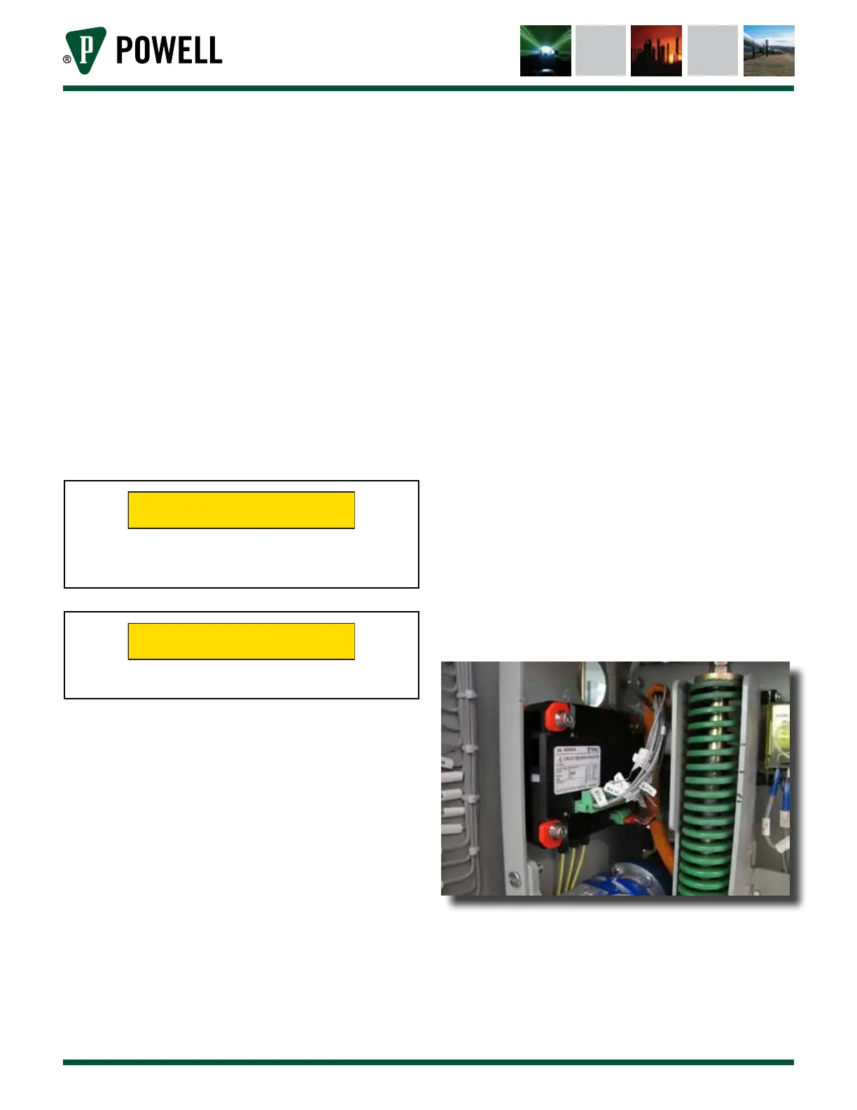
d. MountInG
The mounting location for the Circuit Breaker
Monitor is typically in the top left corner of the
circuit breaker, against the front (Figure 12).
The bolt hole pattern (Figure 13) for mounting
the Circuit Breaker Monitor should be prepared
prior to mounting.
Figure 12 Typical Mounting Location