10
Equipment Description
Powered by Safety
®
Circuit Breaker Monitor
01.4IB.48070A
Table B Hall Effect Input Connections
Pin Number Description
1 +5V Power for HE
2 Ground for HE
3 Digital HE Signal
4 Shield for HE
Table C CBM LED Indicators
Color Description
Green Flashing - Operating as Expected
Red Interacting with Flash, DO NOT POWER OFF
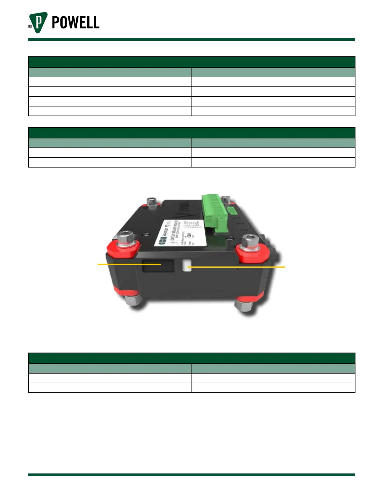
Figure 8 IR Transceiver Window and LED Indicator Location
a
b
a. IR Transceiver Window
b. LED Indicator
Table D Hall Effect Module LED Indicators
Color Description
Green Operating as Expected
Red Initializing or Calibration Mode