16
Installation
Powered by Safety
®
Circuit Breaker Monitor
01.4IB.48070A
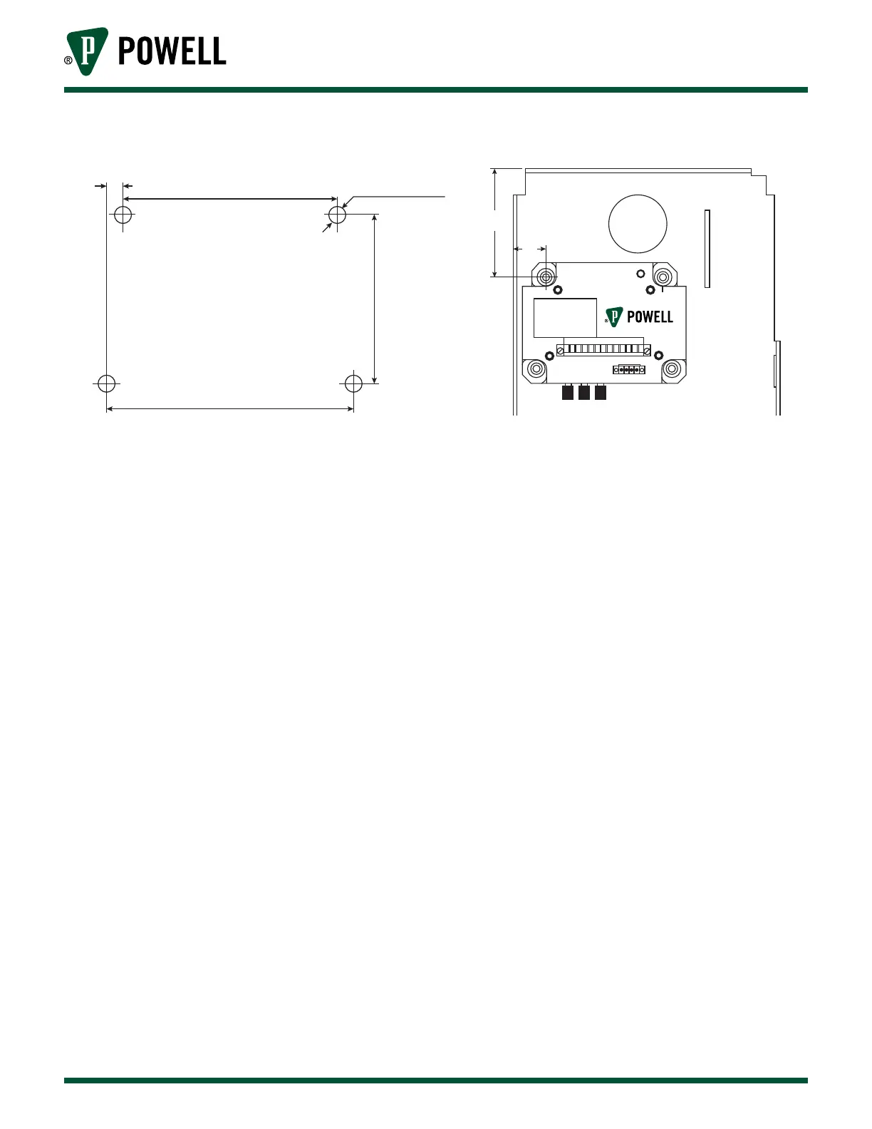
Figure 13 CBM Bolt Hole Pattern
0.275 in
3.80 in
4.35 in
2.97 in
Ø 9/32 in
1 2 3
3.55
1.06
e. BrIteSpot® SlIdInG contAct teMperAture
The BriteSpot fiber probe will be mounted to the lower primary adjacent to sliding contact of each
phase in the circuit breaker. Each fiber probe will also be connected to the BriteSpot input of the
Circuit Breaker Monitor. Perform the following to install the fibers:
1. Route the fiber towards the Circuit Breaker Monitor as shown in Figure 14.
2. To connect the fiber probe to the Circuit Breaker Monitor, unscrew the knob of the BriteSpot
input, place the fiber into the hole of the knob and retighten the knob.
For additional BriteSpot support, refer to the latest version of the BriteSpot instruction bulletin.