8
Equipment Description
Powered by Safety
®
Circuit Breaker Monitor
01.4IB.48070A
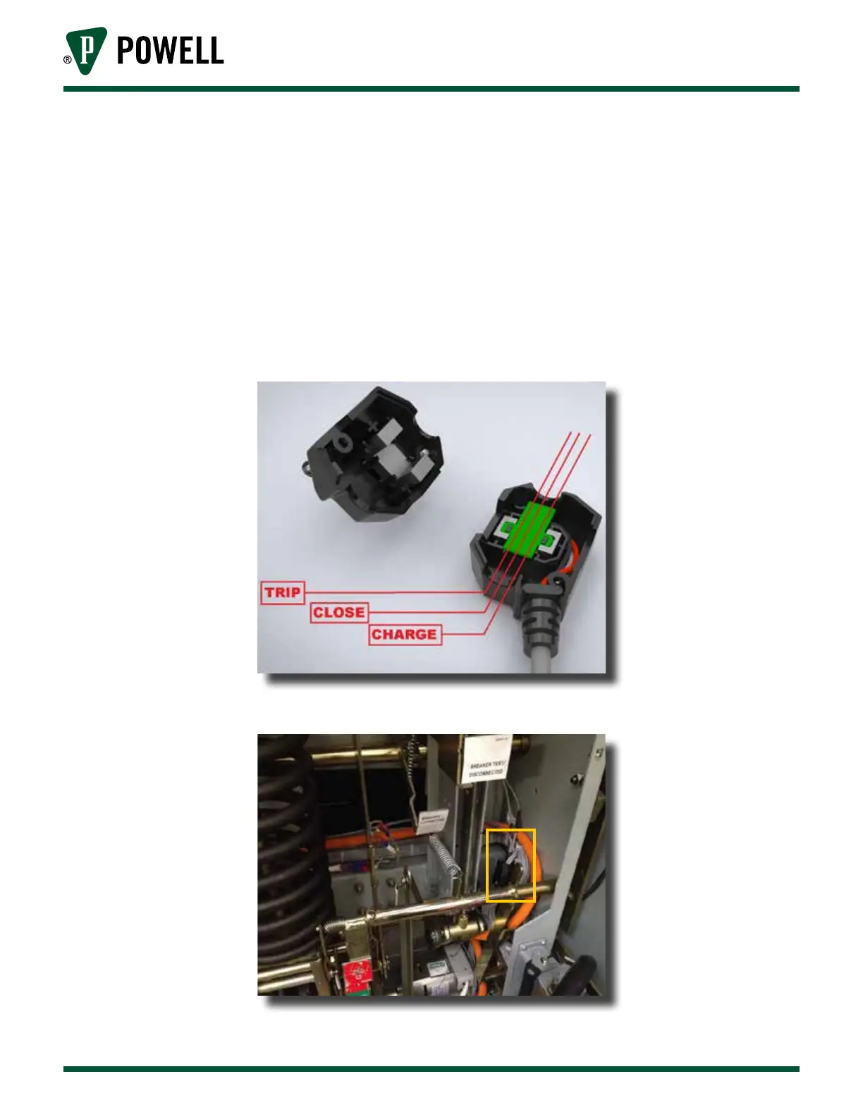
B. HAll effect SenSor
The Hall Effect Sensor module is mounted within the wire bundle directly behind the circuit breaker's
secondary disconnect. In order to provide a consistent polarity signal the positive (+) polarity leads
for the charging motor, close coil and trip coil are placed within the sensor (Figure 5).
The lead from the sensor is to be laced to the existing wire bundle. The lead will traverse the breaker
frame from right to left with the wire bundle that passes from near the secondary disconnect where
the sensor is attached to the upper left side of the frame where the
Circuit Breaker Monitor is mounted.
Figure 5 Hall Effect Sensor Module Wires
Figure 6 Hall Effect Sensor Module Installed