18
Installation
Powered by Safety
®
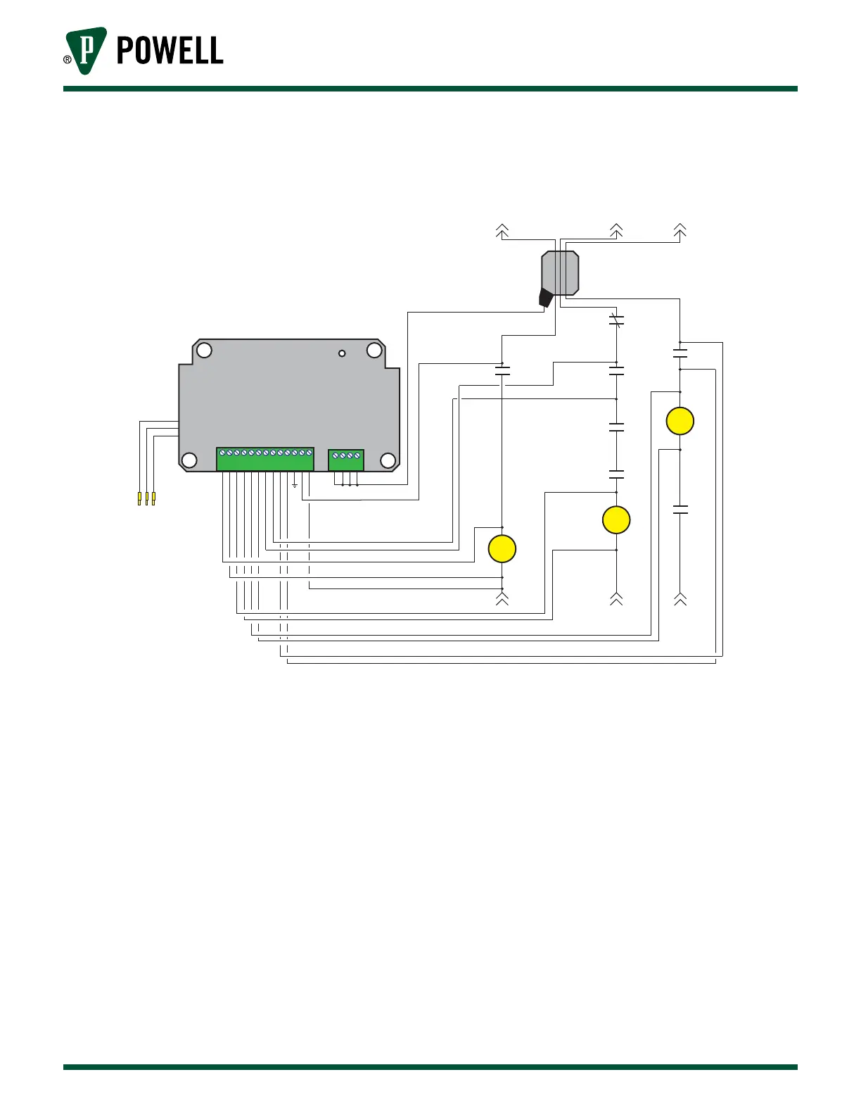
Circuit Breaker Monitor
01.4IB.48070A
Figure 15 Typical Circuit Breaker Monitor Wiring Diagram
1
2
3
4
5
6
7
8
9
10
11
12
13
1
2
3
4
CBM
TO CIRCUIT BREAKER
TO HE SENSOR
CH1
CH2
CH1
BRITESPOTS
IRDA
RH SENSOR
LS
LS
52B
LCS
52A
52A
Y
CBM 13
CBM 4
CBM 2
CBM 3
CBM 5
CBM 6
CBM 9
CBM 10
CBM 8
CBM 7
CBM 1
CBM 12
M
CC
TC
HE
Hall Eect Sensor
NOTE: Wire numbers shown are for the secondary disconnect
Secondary
Disconnect
G. MountInG And plAceMent of IrIM And eIM
The placement of the IRIM on the inside of any door requires that the infrared window of the IRIM
be within a 20 degree angle of the associated Circuit Breaker Monitor infrared window line of sight.
The shortest distance from the CBM to the IRIM (when the breaker is in the racked out position) will
determine the most restrictive placement of the IRIM.