9
Equipment Description
Powered by Safety
®
01.4IB.48070A
c. InputS And IndIcAtorS
Table A Main Input Connections
Pin Number Description Function
1 +ve Supply to Charge Motor
Analog Voltage Input
2 -ve Return from Charge Motor
3 +ve Supply to Close Coil
Analog Voltage Input
4 -ve Return from Close Coil
5 +ve Supply to Trip Coil
Analog Voltage Input
6 -ve Return from Trip Coil
7 Digital Input A for LCS Contact
Digital Sense Input
8 Digital Input B for LCS Contact
9 Digital Input A for 52A Contact
Digital Sense Input
10 Digital Input B for 52A Contact
11 Chassis Ground Local Chassis Ground
12 +ve Supply to CBM
Supply Voltage
13 -ve Return from CBM
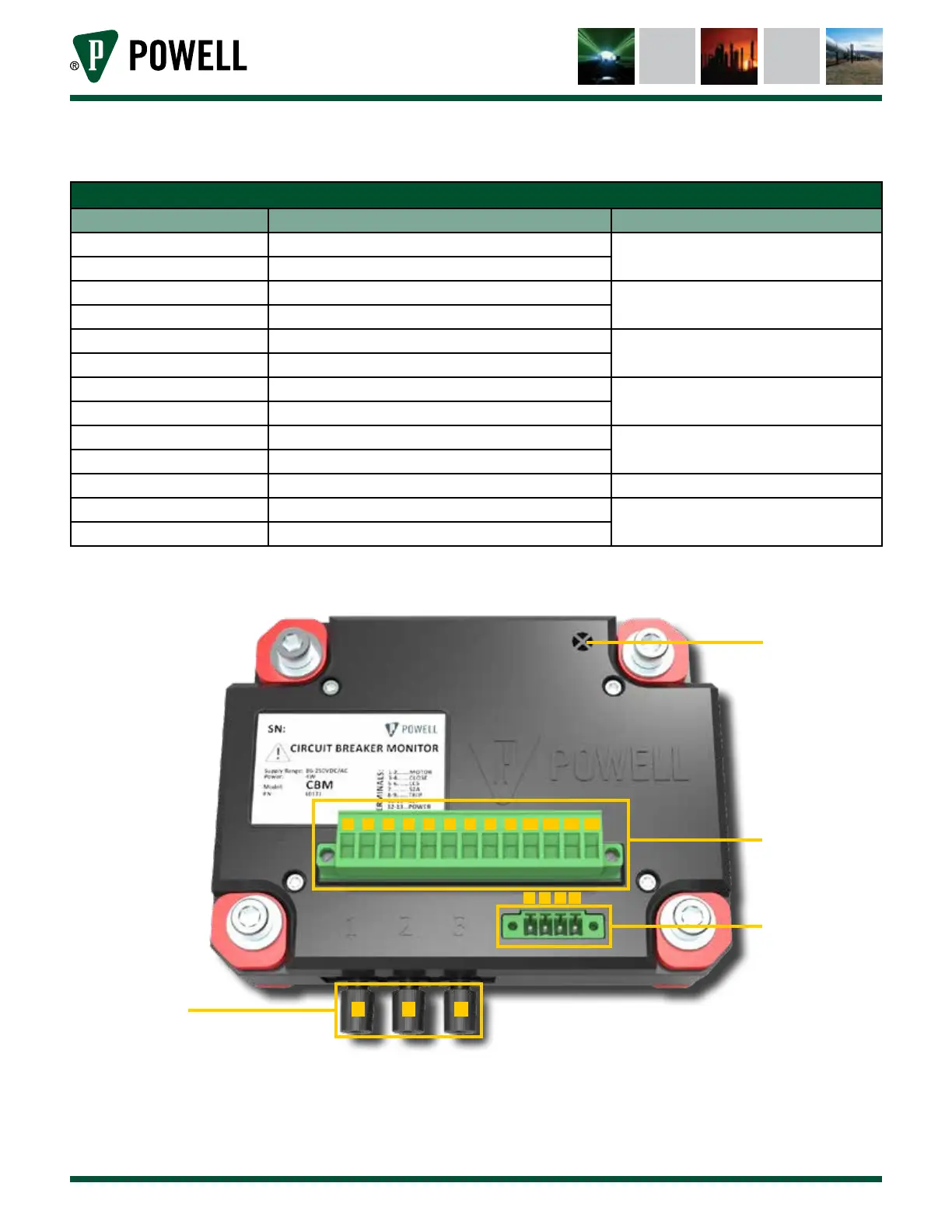
Figure 7 Circuit Breaker Monitor (CBM) Input Connections
a. Temperature Sensor
b. Main Inputs
c. Hall Effect Sensor Connection
d. BriteSpot® Inputs
a
b
c
d
1 2 3 4 5 6 7 8 9 10 11 12 13
1 2 3 4
1 2 3