19
Installation
Powered by Safety
®
01.4IB.48070A
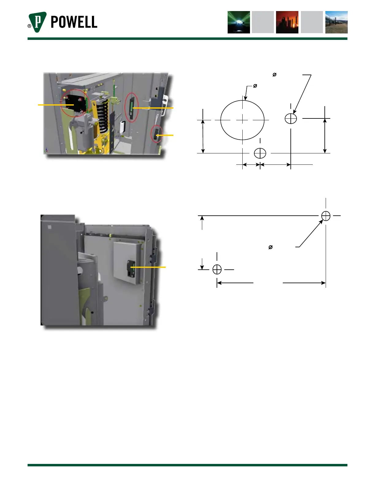
Figure 16 Mounting Locations of IRIM and CBM
a
b
c
a. Circuit Breaker Monitor (CBM)
b. Infrared Interface Module (IRIM)
c. External Interface Module (EIM)
Figure 17 IRIM Mounted on Inside of Door
a
a. Infrared Interface Module (IRIM)
Figure 18 EIM Mounting Hole Pattern
20.8 [0.82 in]
6.6 [0.26 in]
25.4 [1.00 in]
22.0 [0.87 in]
18.0 [0.71 in]10.2 [0.40 in]
Figure 19 IRIM Mounting Hole Pattern
38.2 [1.50 in]
92.2 [3.63 in]
6.6 [0.26 in]