SD700 – TOUCH-GRAPHIC DISPLAY
POWER ELECTRONICS
16
APPLICATION MANAGEMENT
Title Bar
From left to right (see figure 2.1):
Power icon ‘P’ (Power logo): When the user taps on it, the system menu is shown.
Title: This bar shows the drive rated voltage and current, or the name of the visualized
window depending on the visualized screen. For example, if the initial screen is on the
Visualization Area, this bar will show the drive rated voltage and current, but after accessing
to any menu, the name of which is shown on the Title Bar.
Help button ‘?’: It displays the Help Screen on the Visualization Area.
Back button ‘Í’: To return to the previous screen.
Status Bar
It shows the main status indicators of the drive. From left to right (see figure 2.1):
Drive status: Drive operation status, warnings and trips (see chapters ‘8. STATUS
MESSAGES’ and ’12. FAULT MESSAGES. DESCRIPTIONS AND ACTIONS’ of the SD700
‘Getting Started Manual’ for further information).
Average motor current: It shows the average current consumption by the motor in Amps.
Actual motor speed: It shows the actual motor speed as %. The sign indicates that the motor
rotates in a direction. A positive sign does not only mean that the motor rotates clockwise.
Visualization Area
This area is where the different application menus (configuration and visualization), drive
parameters and configuration options are shown. It is also used for the Help and Fault log
screens (see figure 2.1).
2.1.2. Floating Menus
A Floating Menu is a group of commands related between them arranged in columns. There are
only two types of them in the application:
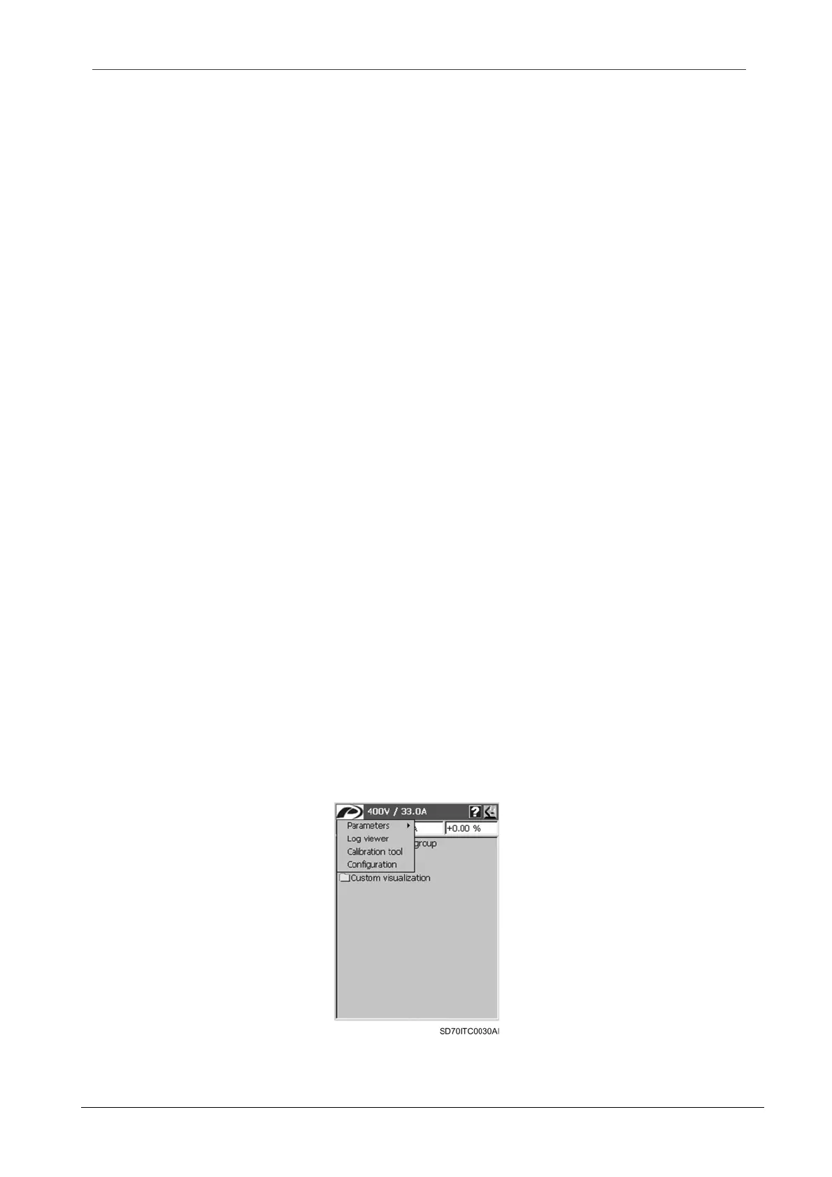
System menu: Main configuration and system tools menu of the graphic display. It is
accessed just tapping the ‘P’ icon. From this menu the user can:
o Manage the parameter files.
o View the fault logs.
o Calibrate the LCD’s Touch Panel
o Set up the language of the display and the SMS service
Figure 2.2 System menu
 Loading...

