VS65
POWER ELECTRONICS
50
ANNEXE A. POWER CABINET OPERATION
Remark: the No.0000 is event number, 02-06-26 is the date when the event occurred, that
corresponds to year–month–day.11:21:22.525 is corresponding to hour-minute-second-
millisecond.
By the “↑”, “↓” to display all events. If the type of event is protection operation, press “enter” to
check the operation value, and then press the key “Ext” to return.
04 In and Out
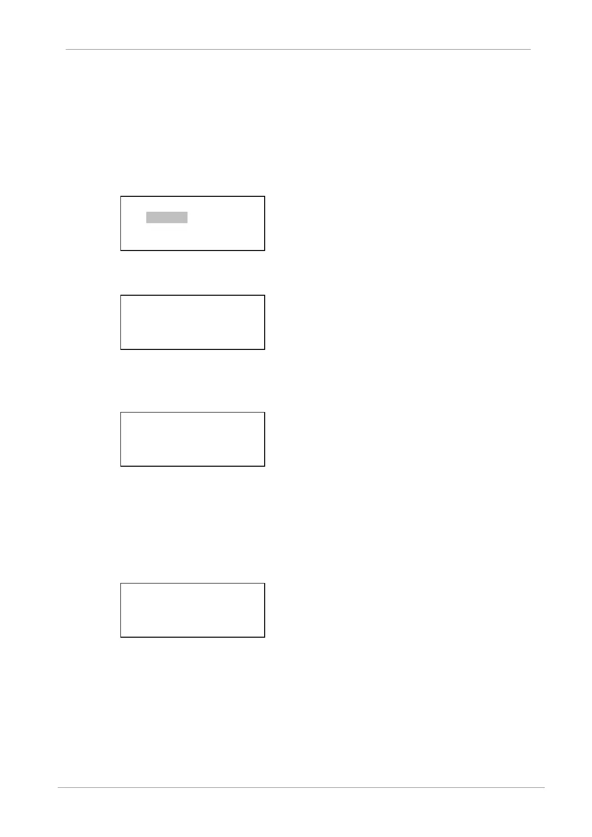
Select the “In and Out” submenu and then display as below:
By the key “↑”, “↓” to check the input operation or the output operation. When choose the digital
input, the display as below:
Remark: “0” means that the switch is not closed, “1” means that the switch is closed. In the picture
showed above, the No.7 and No.13 digital inputs are “1”, others are “0”.
Pressing the key “Ext” will return to the previous menu.
When choose the digital output, the display is as show:
By the key “↑”, “↓”, “←”, “→” to select the digital output and modify the output status. The “1” is
closed or the indicator is ON, the “0” is opened or the indicator is OFF. After modifying, you have
to press “enter” and confirm the password, then press “enter” again, the corresponding relay will
be operated.
05 Sample
Select the “Sample” submenu and then the display as below:
Because the screen only show 4 lines, you can use the key “↑”, “↓” to select the sample data.
Normally, the channel “0” will measure the current of phase A, the channel “1” will measure the
current of phase B, the channel “2” will measure the voltage of phase A, the channel “3” will
measure the voltage of phase B, the channel “4” will measure the voltage of phase C, the channel
“5” will measure the protection current of phase A, the channel “6” will measure the protection
current of phase B, the channel “7” will measure the protection current of phase C. The channels
8 to 12 are different in the different types of device. Please refer to the real time display of
sampling.
1. Input
2. Output
Digital Input
01 – 08: 00000010
09 – 16: 00001000
Digital Output
FEDCBA9876543210
00000000000000000
0 5.00 5.01
2 56.80 57.02
4 56.87 4.98
6 4.78 5.11