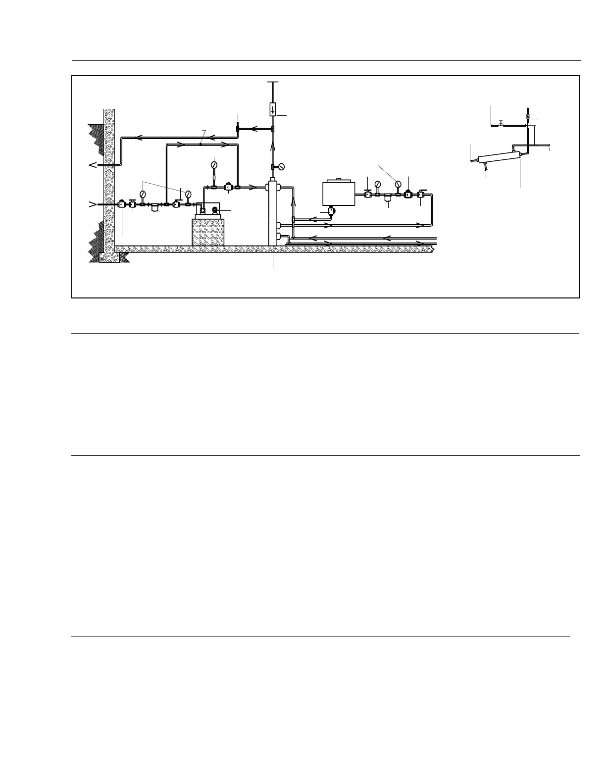
Multiple Burner System Oil Piping Schematic (Flooded Suction)
Figure 12
Combustion Chamber - General
Combustion chambers shall be provided as
recommended in Chamber Dimension Charts, and
should be constructed of high temperature refractories,
in the form of firebrick or rammed plastic refractory,
backed by suitable heat insulating material.
Certain types of heat exchangers, such as warm air
furnaces, some hot oil heaters, wet base steel and cast
iron packaged firebox boilers and Scotch marine boilers,
use the combustion chamber to transfer heat, and
therefore do not require refractory or other insulation.
If in doubt, consult the heat exchanger equipment
manufacturer.
Where boilers are of the mud-leg type, refractory should
extend 6" to 8" above the bottom of mud-leg.
All possible points of air infiltration or ex-filtration must
be sealed. If the unit is to be fired under positive
combustion chamber conditions, extreme care must be
taken to ensure that a 100% seal is maintained.
The Type C burner is designed to provide all the air
required for complete and efficient combustion.
Entry or loss of air from sources other than the firing unit
will decrease its overall combustion and operational
efficiency. See page 14, Figures 13 through 16 and
Table 7 for additional information.
Return
to Tank
Inlet
From
Tank
Press Gauge with
Snubber
Check Valve
Vent
Vacuum Breaker
Return Line
Press Test
Burner
Circulating Oil Reservoir
(May Be Placed Horizontally,
see Detail A)
Additional
Burners as
Req’d.
Detail A
Vent
Vacuum
Breaker
12” Min.
Fresh air required to support combustion, as well as to
provide adequate location ventilation, must be supplied.
All types of fuel require approximately 12 cubic feet of
standard air (sea level at 60 F
o
) per 1000 BTUs firing rate,
for theoretical perfect combustion. In actual practice,
a certain amount of excess air is required to ensure
complete combustion, but this can vary substantially
with specific job conditions. Additional air is lost from
the boiler room through barometric dampers, draft diverters
and similar venting devices. It is generally accepted that
½ square inch of free air opening (for each gas or oil
burner in the room) per 1000 BTU/hr. firing rate will be
adequate. Under no circumstances should a boiler
room be under negative pressure. Jurisdictional
authority relating to combustion air and boiler room
ventilation requirements vary widely. In order to make
certain of compliance, review NFPA-54 and the controlling
authorities should be consulted.
Combustion Air Requirements
Burner Mounting - General
A properly installed and adjusted burner is the lowest cost
maintenance insurance you can buy.
Provisions should be made to provide adequate space
around the burner and associated equipment to allow for
ease of inspection, maintenance and service.
Observe codes for the minimum clearances to combustible
materials.
Provide a suitable burner front plate, consisting of a steel
plate of ample thickness to support the weight of the burner
and hold it firmly in alignment with the heat exchanger. The
front plate must be protected from heat using high temperature
refractory on firebox side (as applicable).
To install the burner, a circular opening must be cut in the
steel front plate. Four (4) mounting bolts must be
installed at proper locations to match the mounting holes
provided on the burner mounting flange. (See dimen-
sional drawings, page 5.) The burner mounting flange
must be securely attached to the front plate with suitable
gasket or non-asbestos, high temperature rope packing to
prevent any products of combustion from escaping from
the combustion chamber. The burner assembly should
be supported at the base of the housing to prevent undue
strain on the front plate. (A mounting pedestal is furnished
for this purpose.)
Type C burners are furnished with a lifting lug for ease of
handling and mounting.
Compound
Gauges
Standby Equipment
Same as Shown Below
Shut Off
Valve
Check Valve
Oil
Strainer
or Filter
Power
Flame
Pump Set
Fusible Valve
Strainer
Shut
Off Valve
Check Valve
Compound
Gauges
From
Supply Pump
Connection
To Tank Return
To Burner Pump
Suction Connection
Pitch ¼” Per Ft.
Upward Toward
Return End
To Burner
Pump
Return
Connection
Fusible
Valve
Fill Tee with Plug
(Highest Point)
Check
Valve
Rev.304
C13