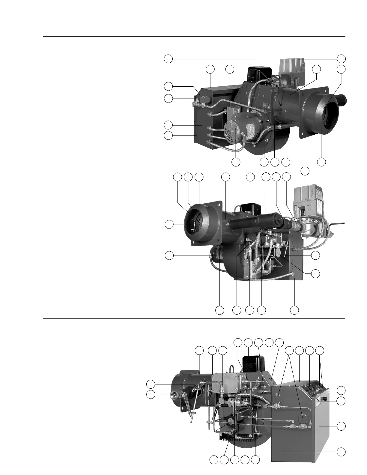
Figure 2
Burner Component Identification
Typical for Model C-GO with Low-High-Off or Low-High-Low Fuel/Air Control Modes of Operation.*
1. Blower Motor
2. Blast Tube
3. Air Inlet Housing
4. Air Flow Switch
5. Air Diffuser
6. Flame Retention Ring
7. Gas Pilot Regulator
8. Gas Pilot Solenoid Valve
9. Gas Pilot Test Tee
10. Gas Pilot Assembly
11. Gas Pilot Ignition Transformer
12. Flame Scanner (Detector)
13. Orifice Tee With Gauge Test Port
14. Motorized Gas Valve (Low-High-Off
or Low-High-Low)
15. Air Damper Drive Linkage Assembly
16. Leakage Test Cock
17. Gas Premix Adjustment (Optional
Feature)
18. Oil Pump
19. Hydraulic Damper Actuator
20. Oil Nozzle
21. Low-High-Off or Low-High-Low Oil Control Train
22. Control Panel
23. Hinged (Total Access) Top Section
24. Removable Total Access Door
25. Test Port
*The components and arrangements shown
are typical for a Model C combination
gas/oil burner. Gas only or oil only
units will have similar components
relating to their specific fuel. In some
cases, the type of components and/or their
arrangements may vary from this depiction.
For specifics on your system, refer to the
technical information supplied with the
burner.
Figure 3
Burner Component Identification
Typical for Model C-GO with Modulating Fuel/Air Control Modes of Operation.*
1. Blower Motor
2. Blast Tube
3. Air Inlet Housing
4. Air Inlet Damper Cross Connecting Linkage
5. Air Flow Switch
6. Flame View Port
7. Drawer Assembly Cover Plate
8. Drawer Assembly Adjustment
9. Air Diffuser
10. Flame Retention Ring
11. Gas Pilot Regulator
12. Gas Pilot Solenoid Valve
13. Gas Pilot Test Tee
14. Gas Pilot Assembly
15. Gas Pilot Ignition Transformer
16. Flame Scanner (Detector)
17. Modulating Butterfly Gas Valve
18. Modulating Drive Motor
19. Jack Shaft and Drive Linkage
20. Gas Pressure Gauge Test Port
21. Gas Premix Adjustment (Optional
Feature)
C4
Rev.703
23 4
5
8
7
22
24
5
6
2
1
12
16
14
6
10
19 21 22
18
15
1
3
8
715
6
3
32
27
22
25
4
20
17
2
2
1411
9
30 29
28
12
24
19
26
12
13
11
25
17
20
18 35
31