Table 1
Standard Dimensions (Inches)
A
34
1
/8
39
1
/
8
44
50
50
49
7
/8
51
11
/16
56
9
/
16
B
3
13
/16
4
1
/2
5
1
/
4
6
1
/4
6
1
/4
6
1
/
4
8
1
/8
8
1
/8
B(R)
5
9
/
16
6
1
/8
7
7
5
/
16
7
5
/16
7
5
/16
10
1
/
8
10
1
/8
C
14
1
/
2
14
7
/8
16
5
/
8
18
7
/
8
18
7
/8
18
7
/
8
24
5
/
16
27
1
/8
C(R)
14
1
/
2
14
15
1
/
4
17
11
/
16
17
11
/16
17
11
/
16
22
3
/
8
27
5
/8
D
4
5
/
8
5
1
/4
6
7
7
7
3
/4
8
3
/
4
8
3
/4
E
12
1
/
4
14
16
18
1
/
2
18
1
/2
19
7
/
8
18
20
Gas/
Oil
20
20
22
3
/8
28
26
1
/2
26
1
/2
21
13
/
16
24
3
/8
STD
3
1
/
4
4
4
1
/
2
6
6
5
4
7
/
8
3
1
/4
K
10
1
/
4
10
1
/4
10
1
/
4
10
1
/
4
10
1
/4
10
1
/
4
9
1
/
8
9
1
/8
X
7
1
/
4
8
1
/2
10
12
12
13
1
/2
13
1
/
2
13
1
/2
H
7
1
/
4
8
3
/4
10
1
/
8
12
1
/
8
12
1
/8
13
5
/
8
15
5
/
8
15
5
/8
ST.
Oil
12
3
/4
13
14
1
/
4
18
18
18
21
13
/16
24
3
/8
I
7
3
/
8
8
1
/2
11
1
/
2
14
1
/
4
14
1
/4
14
1
/
8
13
7
/
8
12
1
/4
L
17
1
/8
18
7
/
8
22
26
5
/8
26
5
/
8
26
1
/2
26
1
/2
24
7
/
8
S
12
5
/
8
13
3
/8
15
1
/
2
19
1
/
8
19
1
/8
19
19
17
5
/16
MAX*
4
3
/4
6
3
/
4
8
9
9
11
3
/4
11
1
/4
9
5
/
8
F** G
C5
11
12
32
30 5
15
33
2
1
16
23
10
* This dimension may be increased. Consult factory.
Note: Dimensions shown are standard, but may vary due to
component changes, etc.
** This dimension depicts space required to accommodate
a standard gas train, standard oil valves and standard
burner mounted pump.
Rev.304
Model
C1
C2
C3
C4
C5
C6
C7(B)
C8
34
9
13
14
NOTE:
Add
3
/
8
" to “H” for size of opening in
boiler front plate.
* Dimension may be reduced by 10
1
/4" by
moving panel to appropriate alternate
location.
5
/
8
” Dia.
4 Holes
5
/
8
” Dia.
4 Holes
Figure 5
Model CR Configuration
Figure 4
Model C Configuration
Standard Burner Dimensional Data
NOTE:
Add
3
/
8
" to “H” for size of opening in
boiler front plate.
* Dimension may be reduced by 10
1
/4" by
moving panel to appropriate alternate
location.
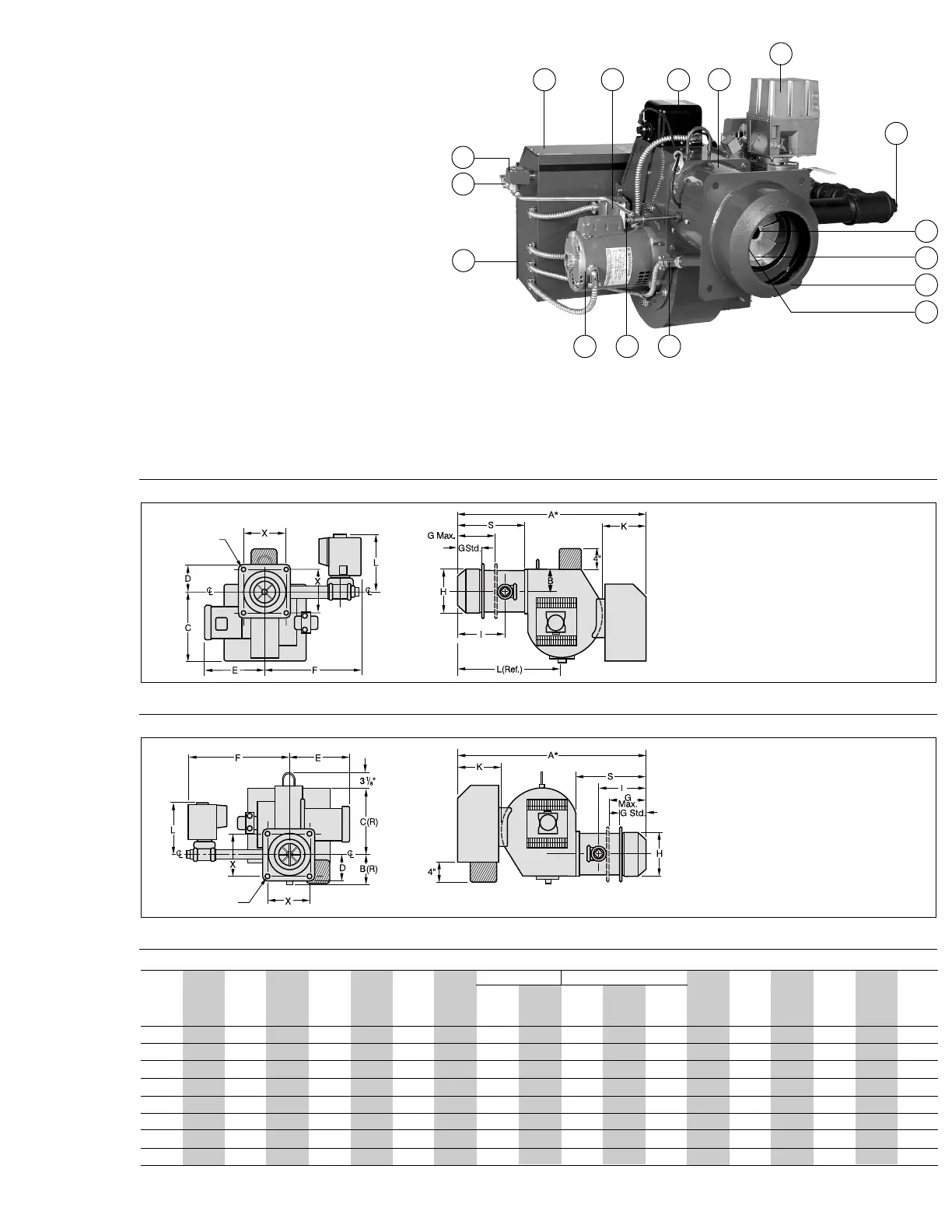
22. Oil Pump
23. Oil Nozzle
24. Modulating Oil Valve
25. Oil Nozzle Bypass Pressure Test Tee
26. Nozzle Return Line Check Valve
27. Control Panel
28. On-Off Switch
29. Fuel Selector Switch
30. Hinged (Total Access) Top Section
31. Light and Switch Circuit Board
32. Removable Total Access Door
33. Motorized Gas Valve
34. Test Port
35. Optional Board for Sequence
Indicator Lights
NOTE:
See page 22, Figure 28 for depiction of characterized fuel/air
control system.
*The components and arrangements shown are typical for a
Model C-GO combination gas/oil burner. Gas only (C-G) or oil
only (C-O) units will have similar components relating to their
specific fuel.
In some cases, the type of components and/or their
arrangement may vary from this depiction. For specifics on
your system, refer to the technical information supplied with
the burner.
CAD
ST.
Oil
11
11
1
/2
-
-
-
-
-
-