Ignition Electrode &
Porcelain Insulator
Stainless Steel
Fan Diffuser
1
/
16
”
1
/
8
” N.P.S. Brass Pipe
Ignition Electrode Support
1
/
4
” From Nozzle Tip to Electrode Tip
Nozzle
Typical Electrode Setting
For Most Non-Pressurized
Combustion Chambers
5
/
16
”
1
/
4
”-
5
/
16
”
5
/
16
”
5
/
16
”
3
/
16
”
Typical Electrode Setting
For Most Pressurized
Combustion Chambers
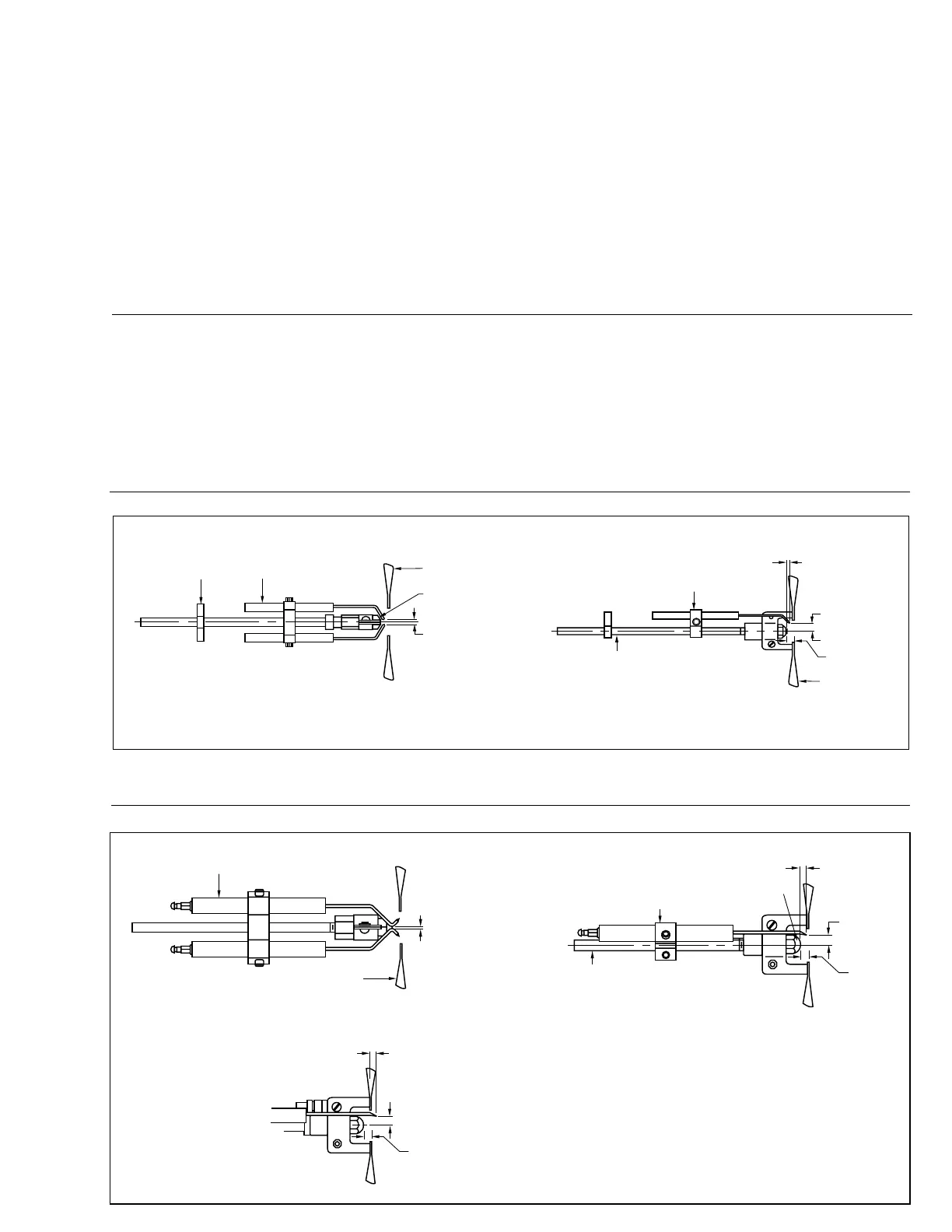
Figure 31
Oil Drawer Assembly Jacobs Ladder Electrode Settings
Figure 30
Oil Drawer Assembly Tip Point Ignition Electrode Setting
Cable Routing
Bracket
Ignition Electrode &
Porcelain Insulator
(Optional)
Certain OEM applications may require
alternate settings. Setting of electrodes
closer to center of nozzle and/or farther
forward may be required.
Stainless Steel
Fan Diffuser
Nozzle
1
/
8
” to
3
/
16
” Gap
Ignition Electrode
Support
1
/
8
” N.P.S. Brass Pipe
Stainless Steel
Fan Diffuser
5
/
16
” for
60
o
Nozzle
1
/
4
” From Nozzle
Tip to Electrode
Tip
3
/
8
” for
80
o
Nozzle
5
/
16
”
Direct Spark Oil Ignition Adjustments
1. The ignitor assembly should be removed and
cleaned regularly. The porcelain insulators should
be kept clean and must be replaced if cracked.
2. The spark gap must be set in accordance with the
dimensions noted. (Refer to Figures 30, 31, 32).
Ensure that the distance between the electrodes and
the nozzle (or diffuser) is greater than the spark gap.
3. The electrodes should not extend closer than
1
/
8
" to
the spray angle of the nozzle to prevent carboning.
A nozzle spray angle check card is available and
may be used to check electrode position.
4. The high tension wires and clips between the
transformer and ignitor electrodes should be
checked periodically for deterioration.
PUMP LEAKS
1. Cover bolts need tightening; gasket broken or
defective
2. Mechanical seal (used on certain models) may be
scratched, due to dirt
3. Inlet head pressure too high. Install a pressure
reducing valve set at 3 psig or less
4. Oil line fitting not tight
CAPACITY TOO LOW
1. Suction lift too high (see page 12, Figure 10)
2. Air leak in suction line
3. Suction line too small (see page 12, Figure 10)
4. Check valve or strainer is obstructed or dirty
5. Mechanical defects - pump badly worn or seal
defective
For additional oil pump information, refer to the oil pump
manufacturer’s product bulletin supplied with the burner.
C35
Rev.304