Low Fire Operating Position Adjustment in addition to the
light off and high fire operating positions. (See manufacturer’s
bulletin included with the burner.)
An additional temperature or pressure controller is added
to the system, which at a selected preset point will electrically
switch the Motorized Gas Valve and Air Dampers (3) to either
the low fire or the high fire position, as the system load
demand requires. Depending on system load conditions,
the burner can alternate indefinitely between the low and
the high fire positions without shutting down. When the
system demand is satisfied, the Motorized Gas Valve closes
(normally the burner will be in the low fire position at this
time) and the Air Dampers are returned to the light off
position, in preparation for the next operating cycle. The
Driver Arm (10) connected to the Motorized Gas Valve will
increase the travel of the Air Damper Arm (13) as the
Linkage Rod ball joint (11) is moved away from the Gas
Valve Crank Shaft (12). The travel of the Air Damper
Driven Arm will be increased as the Linkage Rod ball
joint (14) is moved toward the Air Damper Axle Shaft (15).
When adjusting linkage travel, make certain that the
driven arm Linkage Return Iron Weight (16) does not
interfere with the Linkage operation - and that all linkage
components are free from binding.
*
Not shown in this depiction. See page 4, Figure 2.
Note 1
Component operational sequencing will vary with the specific
Flame Safeguard Control being used. Refer to the specific
Flame Safeguard Control bulletin supplied with the burner for
complete information.
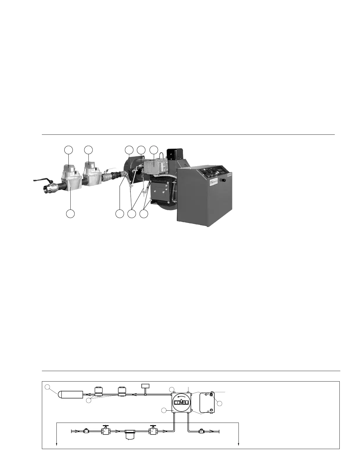
Figure 19
Typical Gas Burner with Full Modulation Fuel/Air Control Mode (Model C-G)
MECHANICAL OPERATION: This Full Modulation system
uses a Diaphragm (1) or Motorized Gas Valves to ensure
opening and positive closure of the gas source to the Blast
Tube (2). A Modulating Motor (3) controls the positioning of
a Modulating Butterfly Gas Valve (4) and movable Air
Dampers (5) through Mechanical Linkage (6). The gas flow
control rate is accomplished through adjustment of the
Main Gas Pressure Regulator (7) and the Butterfly Valve. A
proven spark ignited gas pilot* provides ignition for the
main flame. When the gas pilot has been proven by the
flame detector*, the Diaphragm or Motorized Gas Valve
opens and allows gas at a rate controlled by the Butterfly
Valve to go to the Blast Tube for main flame low fire light off.
After a short period of time at the low fire position, the
Modulating Motor will drive the Butterfly Valve and the Air
Dampers to the high fire position. The burner will stay at
high fire until the system pressure or temperature increases
to a selected preset point, at which time a modulating type
controller will drive the Modulating Motor to low fire, or
whatever firing position between low and high fire is
required to match the system load demand. The Modulating
Motor will continually reposition the firing rate in an effort to
exactly match system load demand. Blast Tube gas pres-
sures can be taken at the
1
/
4
" Plugged Test Port (8) located
between the Butterfly Valve and the gas Blast Tube. Refer to
the Burner Specification computer printout supplied with
the burner, for specific high fire gas pressure values. When
the system pressure or temperature cutoff point is reached,
the Diaphragm or Motorized Gas Valve closes (normally
the burner will be at the full low fire position at this time) and
the Air Dampers will go to the low fire light off position in
preparation for the next firing cycle. This depiction shows
the Linkage in the low fire light off position. Refer to page
22, Figure 27 for information on linkage adjustments. Also
see page 22 for information on the Varicam
TM
modulating
characterized fuel metering system.
* Not shown in this diagram. See page 4, Figure 3.
Note 1
Component operational sequencing will vary with specific
Flame Safeguard Control being used. Refer to the specific
Flame Safeguard Control bulletin supplied with the burner for
complete information.
Figure 20
7
Nozzle
1
Oil Solenoid
Valves
Field Piped
Low Oil
Pressure Switch **
COMBU Oil Pump
2
Pressure Gauge
Test Port
6
Nozzle Port
Vacuum Gauge Port
Optional Inlet Ports
Vent Ports
Vacuum Gauge Port
Return
Port
Inlet Port
Oil
Pump
Side
View
Check Valve
(At Tank)*
Fuel Shutoff
Valve*
Fusible Link Valve
(If Required by Code)*
Filter*
Check
Valve*
Inlet
Return
To Tank
Field
Piped
5
/
32
” Allen Screw
For Oil Nozzle
Pressure
Adjustment
3
* By Others Unless Specified
on Order.
** Burners with Remote Pressure
Atomizing Oil Pumps require a
Low Oil Pressure Switch.
CAUTION:
All field piped components must be
mounted in the proper location and
proper direction of oil flow.
CAUTION:
Oil supply pressure to Burner Pump
must not exceed 3 PSI per NFPA Code.
DO NOT USE TEFLON TAPE
Typical Oil Burner with On-Off Fuel/Air Control Mode
7
4
6
5
2
8
3
1
1
C16
Rev.304