Note 2
Component operational sequencing will vary with the specific
Flame Safeguard Control being used. Refer to the specific
MECHANICAL OPERATION: The RALFS system uses a two
step, two stage dual pressure Oil Pump (6), or fuel unit, with a
simplex nozzle. Either a direct spark or a gas pilot ignition
system may be provided for ignition of the main oil flame.
The air damper is spring loaded to an open position suitable
for maximum desired capacity and proper combustion.
OIL CYCLE: After a 30 second pre-purge is accomplished,
the direct spark ignition transformer is energized. At the
same time the normally closed Cylinder Solenoid Valve (4)
is energized, moving the Hydraulic Cylinder (5) and air
damper to a reduced air setting (combustion air dampers
approx.
3
/8” open). Combustion air is to be set by loosening
the set screws from the damper arm that connects to the
damper shaft. Set the damper opening so as to provide a
smooth and immediate light-off. The amount of combustion
air needed for this temporary setting should be minimal-
just enough to prevent the unit from producing smoke. A
smooth light off with minimal air is the objective. The Low
Fire Pressure Adjustment (7) or the light-off fuel setting
should be set between 90 p.s.i. to 120 p.s.i. After the air
dampers have been driven to the reduced air setting or
light-off fire position the Safety Oil Solenoid Valves (3) will
be energized by the flame safe-guard igniting the low fire
oil flame or the light-off flame which is proven by
flame sensor (scanner). After approximately five
seconds, the normally closed Cylinder Solenoid Valve
will be deenergized, causing the combustion air damp-
ers to open to the fixed air setting for maximum desired
capacity. The return oil valve (normally open) which is
integral to the Suntec two step pump (fuel unit) will now be
energized, providing full high fire oil pressure for the oil
nozzle. At the same time, the main oil valve terminal
on the flame safeguard will be energized and the
Safety Oil Solenoid Valves will open. The adjustment
for fixed air setting or full fire position will be made
with the two bottom
1
/4-20 hex nuts - see item #1.
Combustion air dampers should be adjusted to provide
11
1
/2 to 12
1
/2% CO
2
or 4 to 5
1
/2% O
2
at full input (oil high
fire rate) with zero smoke. High Fire Oil Pressure (8)
setting should be set to the required p.s.i. for high fire oil
rate (see burner specification sheet for setting). The low
fire should be rechecked for light-off pressure and
performance. The gas combustion will be initiated
(after 30 seconds pre-purge period) by proof of spark
ignited gas pilot (by scanner) which energizes dual gas
safety valves. If input for gas is comparable to oil input
then previous air damper adjustment for oil combustion
should be satisfactory for gas firing.
Flame Safeguard Control bulletin supplied with the burner for
complete information.
Nozzle Pressure Test Port
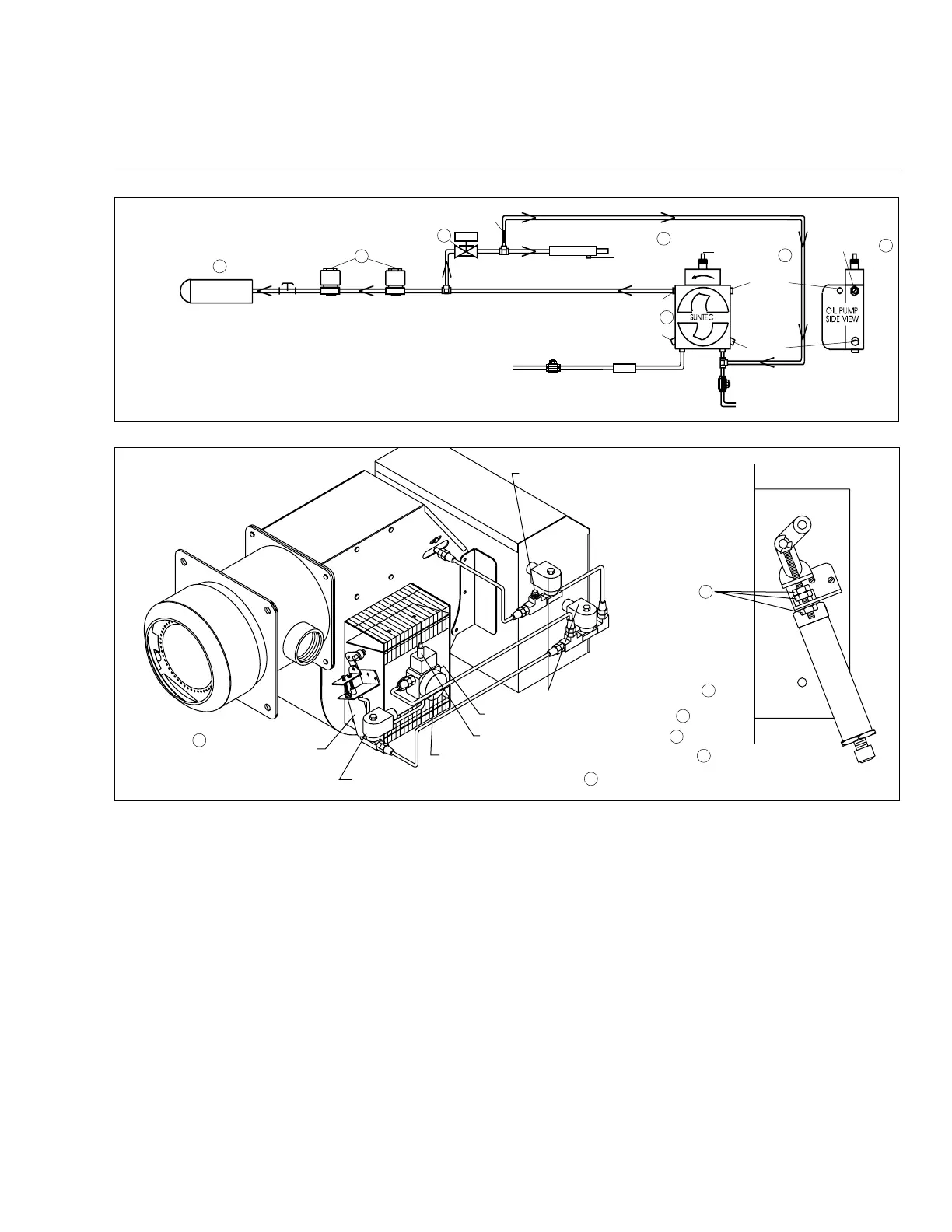
Figure 22
Typical Oil or Gas/Oil Burner with Reduced Air, Low Fire Start RALFS
Simplex Nozzle
Nozzle
Pressure
Test Port
Safety Oil
Solenoid Valves
N.C. Cylinder
Solenoid Valve
#72 Drill Orifice
Hydraulic Cylinder
Atmospheric
Vent
Nozzle Port
Pressure Test Port
Return to Tank
Check Valve
(By Others)
Inlet From Tank
Check Valve
(By Others)
Pressure
Test Port
Optional
Inlet Port
Strainer(By Others)
Low Fire
Press. Adj.
High Fire Oil
Press. Adj.
DO NOT USE TEFLON TAPE
2
3
4
5
7
8
6
Oil Pump
1
Normally Closed Cylinder Solenoid Valve
4
Two-Step (Dual Pressure) Two Stage Fuel Unit
6
Low Fire Oil Pressure Adjustment
7
High Fire Oil Pressure Adjustment
8
3
Safety Oil Solenoid Valves
Hydraulic Cylinder
5
C18
Rev.304