10
DigiMod PFC2 - PFC4 | SERVICE MANUAL
INDEX
Amp stage current consumption
Make sure that the Control Board is properly inserted in
the Module.
Connect the Banana Plugs of the DigiMod PFC AUX
Voltage Cable to the power supply as portrayed on (Fig.
11)
Isolate the remaining banana plugs with a piece of
electrical tape.
Slowly increase the voltage to 30Vdc of each output on
the power supply.
Check the Control Board’s LEDs, they should all be on.
If they aren’t, check the Auxilliary +/-12Vdc.
Check if the current absorption is as follows:
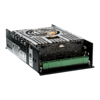
PFC2 (Fig. 11)
80mA ± 10%
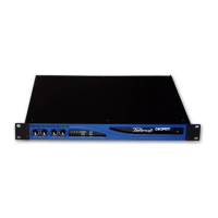
PFC4 (Fig. 12)
140mA ± 10%
In case of out of range absorptions, check the mosfet’s
waveform as indicated on Page 15.
(Fig. 11)
(Fig. 12)
30 V 80mA
30 V 80mA 30 V 80mA
30 V 80mA
ISOLATEDISOLATED
PFC2
30 V 140mA
30 V 140mA 30 V 140mA
30 V 140mA
ISOLATEDISOLATED
PFC4