15
DigiMod PFC2 - PFC4 | SERVICE MANUAL
INDEX
Check of the auxiliary voltage
Checking the Control Board
-12Vdc 5Vdc +12Vdc
-12Vdc
5Vdc
+12Vdc
(Fig. 19)
(Fig. 20)
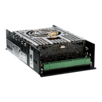
In order to check the AUX Voltages, leave both power
supplies on as for the previous test (120 Vdc) and probe
on the indicated points with a multimeter.
PFC2: (Fig. 19)
PFC4: (Fig. 20)
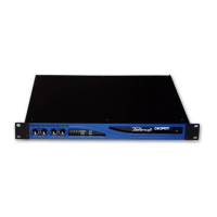
This step is common to both PFC2 and PFC4 modules.
Leave both power supplies on as for the previous test (120
Vdc)
With an oscilloscope probe on the points highlighted on
(Fig. 21), measuring the 12.288 MHz signal of the control
board’s quartz.
Repeat the procedure on each Control Board (PFC4).
(Fig. 21)
Model Kit Number Description
DigiMod PFC2
KT000890.R KIT DM PFC2 PSU
DigiMod PFC4
KT000843.R KIT DM PFC4 PSU
Please refer to the following table when ordering the
repair Kit.