14
DigiMod PFC2 - PFC4 | SERVICE MANUAL
Checking the Control Board’s LEDs
Checking the rail’s voltages
D3
D4
D5
D102
D202
D100
D200
LED ID TYPE DESCRIPTION IDLE MODE SIGNAL MODE
D3 Status Auxiliary +12 V active ON ON
D4 Status Auxiliary +5 V active ON ON
D5 Status Auxiliary –12 V active ON ON
D102 Protection Control Board protection engaged on CH 1 NORMALLY OFF NORMALLY OFF
D202 Protection Control Board protection engaged on CH 2 NORMALLY OFF NORMALLY OFF
D100 Status Current calibration / current drawn by CH 1 NORMALLY OFF BLINK
D200 Status Current calibration / current drawn by CH 2 NORMALLY OFF BLINK
+58.5Vdc -58.5Vdc
+58.5Vdc -58.5Vdc
The following applies to both the PFC2 and PFC4 models.
Leave both power supplies on as for the previous test (120
Vdc) and check the control board’s LEDs by referencing
the table portrayed on (Fig. 16).
(Fig. 16)
Leave both power supplies on as for the previous test (120
Vdc)
By means of a multimeter, measure the rail voltages by
probing on the points indicated on:
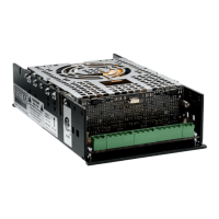
PFC2 - (Fig. 17)
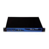
PFC4 - (Fig. 18).
Both modules should read:
CH1 (Left Hand Side) +58.5Vdc
CH2 (Right Hand Side) -58.5Vdc
(Fig. 17)
(Fig. 18)
Model Kit Number Description
DigiMod PFC2
KT000890.R KIT DM PFC2 PSU
DigiMod PFC4
KT000843.R KIT DM PFC4 PSU
Please refer to the following table when ordering the
repair Kit.
INDEX