Settings | 19
left of the rst line. By pressing the up and down pointing
arrows, it is possible to move from one lter to the next. The
lter parameters are reported on the screen.
Active: determines if the lter is enabled or not (at
response
Gain(dB): lter gain. Can be set only if the lter is a
peaking or shelving lter. Acceptable values go from
-15 to +15 dB in 0.1 dB steps.
Q factor: quality factor of the lter. This can be set
for all lters except shelving lters. Acceptable values
range from 0.1 to 30 with 0.1 steps.
Bandwidth (oct): the bandwidth of the lter expressed
in octaves around the central frequency. This value is
determined by setting the Q factor.
Type: allows the user to select the lter type:
1. Peaking
2. Low Shelving (3 to 15dB/oct)
3. High Shelving (3 to 15dB/oct)
4. Low pass EQ
5. High pass EQ
6. Bandstop
7. Bandpass
8. Allpass
Frequency
20Hz-20kHz
Gain
±15 dB
Slope
3-15dB/oct
Q
0.1-30
Peaking
Lo-Shelv
Hi-Shelv
Lo-pass
Hi-pass
Band-stop
Band-pass
All-pass
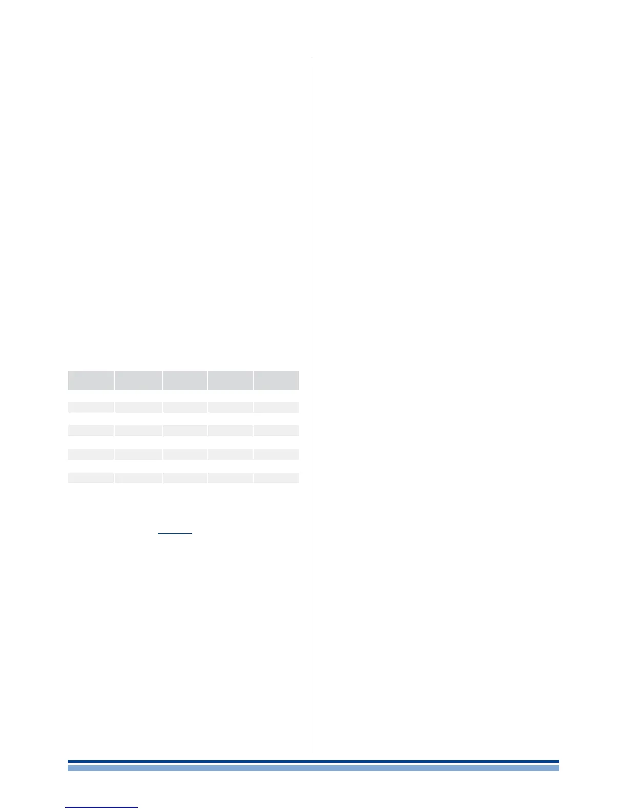
TABLE 7: Filters parameters.
By pressing the “edit” button, the settings for the selected
lter can be modied. TABLE 7 summarizes which param-
eters can be edited according to the selected lter type.
9 : 11.2 . Lo-pass/Hi-pass filters
This menu allows the user to congure the crossover l-
ters. There are 2 available crossover lters: a lowpass and a
highpass. By combining both, the result will be a bandpass
response.
Both traditional Innite Impulse Response as well as
brickwall linear phase Finite Impulse Response lters are
implemented. If a FIR lter in the EQ section is enabled, a
FIR crossover lter cannot be enabled at the same time. The
low pass and high pass lters can be edited (active status,
frequency, slope, lter type) by the user via the main LCD
screen.
The classic IIR crossover lter shapes that can be se-
lected as a high pass or low pass lter are: Butterworth,
Bessel, and Linkwitz-Riley. In the rst 2 cases, the frequency
parameter in the edit window denes the -3 dB point, in the
latter, the -6 dB point. The slope is freely selectable from
a minimum of 6 dB/octave (1st order lter) to 48 dB/octave
(8thorder lter).
The FIR lters can be selected as normal (FIR Linear
Phase) or enhanced (Hybrid FIR). The enhanced version of
the lters gives a higher rejection of out of band signals, at
the expense of a small phase modication (30°@400Hz). In
both cases, the minimum working frequency is relative to
the desired latency. Standard setting limit this to 400 Hz.
For this reason it is advisable to use FIR lters to crossover
upper midranges or mid-high drivers for which the phase
coherency is a key point.
9 : 11.3. Polarity
This menu allows to reverse the signal polarity. The two
selectable modes are:
In phase: the signal’s polarity is not altered
Reversed: the signal’s polarity is reversed.
9 : 11.4. Channel Delay
This menu allows to set a single channel output delay.
This is helpful to time-align two different loudspeakers
on the two output stages. The selectable delay varies from
0 to 32 ms (about 11 meters at 344 m/s sound speed), with
a single sample step (equal to 1/96000th second or 10.4 us,
about 3.5 mm)
9 : 11.5. Gain
This menu changes the channel gain, from -40 dB to
+15dB, with a 0.1 dB step.
9 : 11.6. Limiters
The limiting process in sound reinforcement is a way to
protect loudspeakers from accidental damage; therefore,
limiters are a safeguard against excessive signal peaks
and/or signal power. They not only protect from sudden
signal peaks but also they protect against to an over power
delivering.
Bear in mind that limiting does not only prevent occasional
damage, but it rst and foremost guarantees a long compo-
nent life. The two main purposes of limiting process are:
Limit over-excursion: an impulsive signal can reach the
speakers and cause damage due to over-excursion of
the voice coil that is driven out of the magnetic gap.This
can damage the diaphragm (breaking or deforming it).
Limit over-heating: delivering high power to the voice
coil may lead to overheating. This can damage the iso-
lation or burn out the voice coil. Another evident high
power driving effect is power compression, noticeable
in low frequency speakers.
In order to prevent the mentioned phenomena two kinds
of limiters are provided:
Peak limiter: protects against mechanical damages.
The peak limiter may also be used to control amplier
clipping. Designers should set this limiter’s parameters
as a function of both the maximum displacement
(Xmax) of the diaphragm as well as the speaker’s
maximum tolerated voltage.