▶
10
M Series User Guide
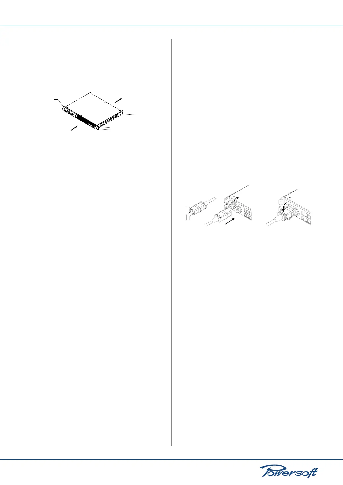
4.2 Mounting
All Powersoft ampliers are designed for standard 19” rack
mounting; there are four front panel holes and two rear-lateral
holes. In order to limit the risk of mechanical damages, ampliers
must be xed to the rack using both frontal as well as rear
mounting holes (see FIGURE 9)
FIGURE 9: Amplier rack mounting holes, front and back
4.3 Cooling
All Powersoft ampliers implement a forced-air cooling system to
maintain low and constant operating temperatures. Drawn by an
internal fan, air enters through the slots in the front panel and is
forced over all components, exiting at the back of the amplier.
The amplier’s cooling system features an “intelligent” variable-
speed DC fan which is controlled by heat sink temperature sensing
circuits: the fan speed will increase only when the temperature
recorded by the sensors rises over carefully predetermined values.
This ensures that fan noise and internal dust accumulation are kept
to a strict minimum. Should however the amplier be subject to
an extreme thermal load, the fan will force a very large volume
of air through the heat sink. In the extremely rare event that the
amplier should dangerously overheat, sensing circuits shut down
all channels until the amplier cools down to a safe operating
temperature. Normal operation is resumed automatically without
the need for user intervention.
Caution regarding heat escape should be exercised when
mounting M Series ampliers. Exhaust cooling air is forced out
through the rear of the chassis (see FIGURE 9); make sure there
is enough space around the back of the amplier for this air to
escape. M Series ampliers can be stacked one on top of the other
due to the efcient cooling system they are equipped with. There
is however a safety limit to be observed: in case a rack with closed
back panels is used, leave one rack unit empty every four installed
ampliers to guarantee adequate air ow.
4.4 Operating Precautions
Make sure the power switch is off before attempting to make any
input or output connections.
Make sure the AC mains voltage used is within the acceptable
operating voltage range specied in the M Series documentation
(factory selected 115 V / 230 V ±15%), depending on your country
mains. Damage caused by connecting the amplier to an improper
AC mains voltage is not covered by the warranty.
By using good quality input and speaker cables, the likelihood of
erratic signal behavior is reduced to a minimum. Whether you
make them or buy them, look for good quality wires, connectors
mounting holes
air flow
mounting holes
mounting holes
and soldering techniques.
4.5 Grounding
There is no ground switch or terminal on the M Series ampliers.
All shield terminals of input connections are directly connected to
the chassis. This means that the unit’s signal grounding system is
automatic. In order to limit hum and/or interference entering the
signal path, use balanced input connections.
In the interests of safety, the unit MUST always operate with
electrical safety earth connected to the chassis via the dedicated
wire in the 3-wire cable. Never disconnect the ground pin on the
AC mains power cord.
4.6 AC Mains Connection
The AC Mains connection is made via the IEC type connector on
the back of the amplier. Please make sure your AC mains power
source operates within the voltage limits indicated on this manual
(factory selected 115 V / 230 V ±15%).
FIGURE 10: Mains connector
Safety warning! Ground wires must be connected! Do not use
adapters that disable grounding.
5 Connections and Operation
5.1 Introduction
This section provides information on amplier connection and
operation. For optimal amplier performance, it is important to
understand the meaning of the information that each M Series
amplier can provide regarding its status and conguration. This
information is available to the user via front panel indicators as
well as through specic LEDs the back of the unit (for DSP version
only). This chapter will break down all the front panel and back
panel functions. The remaining part of the chapter will explain
how to correctly connect the amplier’s inputs and outputs.
5.2 Front Panel Air Filters Access
The blue front panel of all M Series ampliers can be removed
to access the air lters. This is useful when the air lters need to
be cleaned due to dust accumulating and clogging the lters thus
hindering proper air circulation vital for cooling purposes.
To remove the blue colored front panel:
MAINS
GROUND
open the lock and
insert the plug
lock the plug