▶
21
M Series User Guide
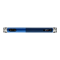
FIGURE 39: The output eq layer.
6.5.4 Limiters
The function of the limiters is to protect voice coils from burning
out due to excess power being delivered over an extended
period of time or from excessively large signal peaks by limiting
the maximum output voltage of the amplier. The limiter window
is accessible by clicking on the limiter block in the device layout
view. Every channel limiter is color coded: blue for channel 1, red
for channel 2, green for channel 3, orange for channel 4.
action is reduced and the gain is returned to normal following
the drop of the output voltage below the threshold level.
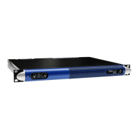
6.5.4.2 Peak Limiter
The function of the peak limiter is to protect voice coils from
excessively large signal peaks by limiting the maximum output
voltage of the amplier. It’s possible set the values of:
▶
Threshold in Volts, is the amplier max output voltage level
corresponding to the maximum displacement of the speaker
diaphragm.
▶
Hold time is the time over which the limiting action is
maintained before the gain level is returned to normal after
the output voltage drops below the threshold.
▶
Release time is the length of time over which the limiting
action is reduced and the gain is returned to normal following
the drop of the output voltage below the threshold level.
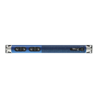
6.5.5 Damping Factor Correction
The effect of cable resistance on a high power amplier
performance becomes signicant at low frequencies, as the cable
resistance can affect the output stage damping factor. Powersoft
Damping Control is a proprietary algorithm which compensates
for cable resistance. The user can enter cable parameters and the
algorithm calculates and applies the appropriate correction. A
tool to calculate the cable resistance is provided. Damping factor
correction can also be used to ne tune how the bass frequency
sounds: a negative resistance leads to a punched bass while a
positive resistance leads to a tailed bass.
FIGURE 41: The damping control window.
The following values can be set by the user:
Enable: enables the correction algorithm
Resistance compensation fader: the negative or positive resistance
value added to the output circuitry.
The cable resistance tool allows to set:
Cable dimensions: enter the gauge of the wire used in the speaker
cable and the cable length into the Wire gauge dropdown list and
FIGURE 40:
The limiters window.
6.5.4.1 RMS Limiter
Electromechanical transducers are highly inefcient; as such
they transform a signicant amount of input power into heat.
The function of the RMS limiter is to protect the voice coils of
speaker drivers from burning out due to excess power being
delivered over an extended period of time. The RMS limiter is set
by selecting a desired maximum power value but acts by limiting
output voltage; by applying Ohm’s law with a xed reference 8
Ohm load, the output voltage level corresponding to the desired
maximum output power value is calculated as the square root of
power times the load resistance (8 Ohm). It is possible to set the
values of:
▶
Threshold in Watts, with respect to an 8 Ohm load.
▶
Attack time is the time between the moment the output
voltage exceeds the threshold and the moment of the onset
of the limiting action.
▶
Hold time is the length of time during which the limiting action
is maintained before the gain returns to normal levels because
the output voltage drops below the threshold level.
▶
Release time is the length of time over which the limiting