▶
20
M Series User Guide
processing of the current device imported in the workspace. For
more information on system conguration, please refer to the
Armonía manual.
The save operation may be seen as a large .pam export of the
entire device; on the other hand, opening a .paw le is equivalent
to performing a large .pam import on multiple devices. The user
will be prompted for multiple realignment decision on any de-
synchronized devices.
If the question is answered with:
▶
yes, the device specied in the window will be aligned to the
data in the .paw le.
▶
yes to all, all the devices will be aligned to the data in the
.paw le.
▶
no, the device specied in the window will NOT be aligned
to the data in the .paw le but the data will be reloaded from
the device.
▶
no to all, all the devices will NOT be aligned to the data in
the .paw le but the data will be reloaded from the devices.
WARNING: during import or preset manager operations the
save .paw function is disabled.
6.5 DSP remote operations
WARNING: due to the internal structure of the system some of
the following le operations can lead to a short audio interruption.
WARNING: all changes will be lost if the preset is NOT stored
on board before unplugging the unit from the mains.
6.5.1 Routing
The input routing is based on the processing layout used: the 1 in
/2 out conguration, for example, allows input on odd channels
only. On the other hand, the 2 in / 2 out conguration allows input
on every channel. In this conguration, a mono mix from both
channels is also allowed: the two channels are added together and
their sum divided by two to normalize the resulting level.
For an MxxD the following congurations are available:
Modules 0
conguration
Input Modules 0 Output Modules 0
1 In / 2 Out Ch1 Ch1/Ch2
2 In / 2 Out Ch1/Ch2 Ch1/Ch2
For an MxxQ the following congurations are available:
Modules 0
conguration
Input Modules 0 Output Modules 0
1 In / 2 Out Ch1 Ch1/Ch2
2 In / 2 Out Ch1/Ch2 Ch1/Ch2
and
Modules 1
conguration
Input Modules 0 Output Modules 0
1 In / 2 Out Ch3 Ch3/Ch4
2 In / 2 Out Ch3/Ch4 Ch3/Ch4
See FIGURE 36 and FIGURE 37.
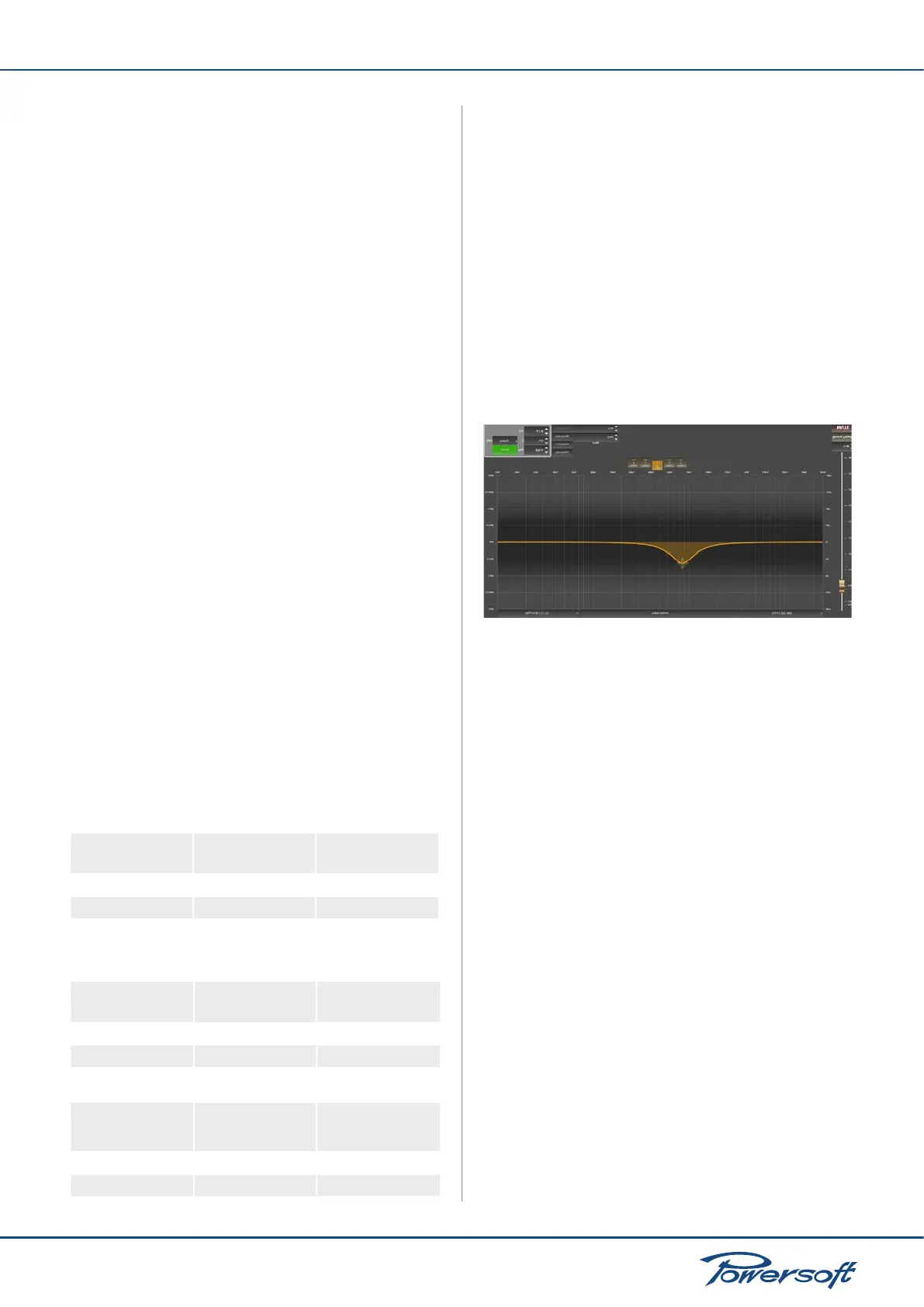
6.5.2 Input Eq.
The input eq. is intended for system operations. The input eq
provides a range of biquad lters that can act as any generic IIR
lter. Refer to Section 5.12.3 on page 13 for more information.
From the input eq page, the frequency response of each channel
can be adjusted in several ways. Discrete time delays can also be
inserted. The presence of every input eq used in the device layout
is reported on the tabbed channel on the bottom left hand side of
the screen. The frequency response curves, together with other
View items, are color coded: blue for channel 1, red for channel
2, green for channel 3, orange for channel 4. Every channel allows
regulation of lters, mute, gain, delay and polarity. The frequency
response (and/or phase response) curve displayed is always
obtained as the combined response of all currently active lters.
FIGURE 38: The input eq layer.
6.5.3 Output Eq.
This page’s general appearance is similar to that of the Input
Equalizer page, but presents several important differences. The
Output Eq. curve the amplier employs is meant to be created from
the speaker manufacturer’s data for the particular loudspeaker
cabinets or arrays the amplier will be driving. It provides a range
biquad lter that can act as crossover or generic IIR lter. Refer to
Section 5.12.3 on page 13 for more information. From this page,
the frequency response of each channel can be adjusted in several
ways. Discrete time delays can also be inserted. The presence
of every output eq. present in the device layout is reported on
the tabbed channel on the bottom left hand side of the screen.
The frequency response curves, together with other View items,
are color coded: blue for channel 1, red for channel 2, green for
channel 3, orange for channel 4. Every channel allows regulation
of lters, mute, gain, delay and polarity. The displayed frequency
response (and/or phase response) curve is always obtained as the
combined response of all currently active lters.