POWERVAR Security Plus UPS
36
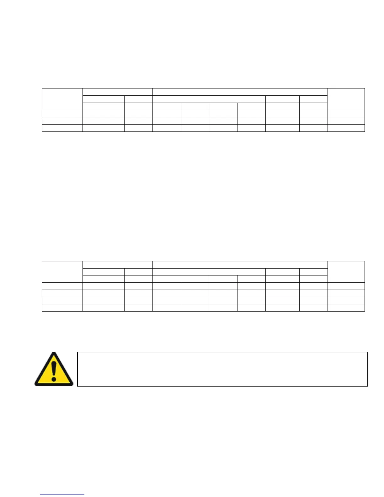
For North American applications, high voltage models may be configured for an input voltage of
either 200, 208 or 240 volts at 50 or 60 Hz. Output voltage for these models is available at
115,120, 200, 208 and 240 volts at 50 or 60 Hz. Table 2-3 illustrates how to connect to the
terminal block in Figure 2-5A to achieve the desired input and output voltage configurations.
VOLTAGE
RATING
INPUT OUTPUT BYPASS
JUMPER
VOLTAGE FREQ VOLTAGE NEUTRAL FREQ
L1 – L2 X1-X4 X1-N N-X4 X2-X4
200 200 50/60 230 115 115 200 N 50/60 208-SSO
208 208 50/60 240 120 120 208 N 50/60 208-SSO
240 240 50/60 240 120 120 208 N 50/60 240-SSO
Table 2-3—North American Connections
NOTE: The neutral to ground connection must be properly connected for a 50 or 60 Hz
configuration. Refer to Table 2-3 (for North American Connections) and table 2-4 (for
International Connections) for the correct neutral to ground connection, as well as the
appropriate voltage and frequency configuration.
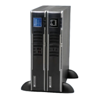
For international applications, high voltage UPS models may be configured for an input voltage
of 200, 220, 230 or 240 volts at 50 Hz. Output voltage for these models matches the input
voltage at 50 Hz. Table 2-4 illustrates how to connect to the terminal block in Figure 2-5B to
achieve the desired input and output voltage configurations.
VOLTAGE
RATING
INPUT OUTPUT BYPASS
JUMPER
VOLTAGE FREQ VOLTAGE NEUTRAL FREQ
L1 – L2 X1-N X1-X3 X3-N X2-N
200 200 50Hz -- -- -- 200 N 50Hz 208-SSO
220 220 50Hz 220 -- -- -- N 50Hz 240-SSO
230 230 50Hz 230 -- -- -- N 50Hz 240-SSO
240 240 50Hz 240 -- -- -- N 50Hz 240-SSO
Table 2-4 – International Connections
If the EP01 and EP02 terminals are inadvertently connected together, this is effectively the
same as activating the EPO switch (shown in Fig.2-5). Doing so will prevent the UPS from
operating. The EPO is designed as a normally open circuit (N/O). If wiring to the EPO circuit a
minimum 16 gauge wire must be used.