POWERVAR Security Plus UPS
41
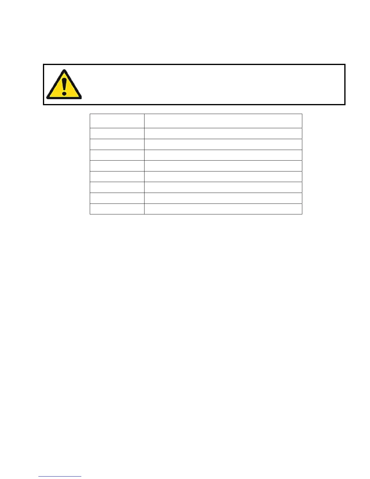
2.1.5 RS232 Communications
The pin-out and signals configuration of the RS232 interface is illustrated in Table 2-5
RS232 Pin # Signal Description
1 Not used
2 Transmit data (TXD)
3 Receive date (RXD)
4 AC fail (normally open)
5 Common
6 Battery low (normally open)
7 AC fail (normally closed)
8 Output, AC fail signal (high to low signal)
Table 2-5
2.1.6 Communication Ports Maintenance
The USB communication port on the back panel of the UPS system is designed to communicate
with a computer or server. Only connect to this USB port if you intend to use POWERVAR’s
monitoring software from a computer or server near the UPS system. The RS232 port is
designed to communicate with a computer or server for the same monitoring capabilities. You
should only connect to the RS232 port of a computer or server. The remote contact interface
port is provided as a set of solid state relay switch contacts. The switches are available through
a DB9 male connector on the rear of the UPS. The chart above shows the pin assignment for
each signal. The EPO (emergency power off) contact is a normally closed 125 VAC circuit.
When wiring to the EPO a properly sized switch must be used. Contact POWERVAR with any
questions
2.2 Basic Principles
When commercial power is normal, UPS input power is routed via the power factor corrected AC
to DC chopper circuit. The chopper circuit increases the voltage to ±380V stabilized DC voltage,
which supplies DC/AC inverter. The inverter changes the DC power back into regulated,
conditioned, sinewave AC power, which is connected to the load equipment via a low impedance
isolation transformer. At the same time, the battery is kept charged by a battery charger. When
commercial power is lost the battery supplies power to the DC buss for use by the inverter. This
assures continuous “no break” power for the connected load. In the event of an inverter
overload or inverter fault, a solid state static bypass switch automatically connects input power
directly to the primary of the output isolation transformer.
UPS operational modes are illustrated in Figures 2-8, 2-9, and 2-10.
Maximum current carrying capacity of the switch contacts is 3A/30VDC.