Installation
38
Powerware
®
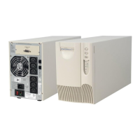
PrestigeSeriesInstallationand Operator’s ManualforIBM Applications (6000 VA)Uncontrolled Copy
6. Plug the input and output power cords of the PPDM into the
input and output power connectors on the PPU rear panel.
Figure 19 on page 52 shows the PPDM and PPU rear panel
connections.
7. The equipment to be protected by the UPS should be powered
off. Plug the equipment into the power output receptacles on
the PPDM rear panel.
NOTES
:
Use theIEC 320-C19/C20 outputcord providedwiththe PPDMto connect the
AS/400 tothe PPDM.
:
You mayhaveto use theoutput cordprovidedwiththe PPDMfor 230V usage.
:
When using thePPDM,itisrecommendedthat the equipment notbe plugged
intothe PPU.
:
Donot protectlaser printers withthe UPS/PPDM because ofthe exceptionally
highcyclicpower requirements ofthe heatingelements.
8. Plug the battery cord into the battery connector on the PPU. All
battery connectors are polarized to prevent incorrect
connection.
9. If additional battery cabinets are to be used, plug the battery
cord of the second cabinet into the battery connector of the first
cabinet after pivoting the battery connector guard out of the
way. Follow this procedure for each additional battery cabinet.
10. Remove the breaker tie from the circuit breaker onall battery
cabinets.
11. If you are using a REPO switch, follow the “REPO Installation”
instructions on page 41.