Chapter 4 Installation and commissioning
17
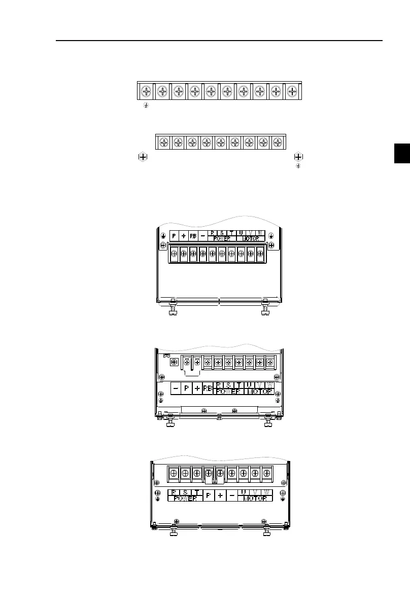
4-3.Main circuit terminal
4-3-1.Main circuit terminal arrangement
1.0.75 to 4kW G3 main circuit terminal
Figuer 4-4:0.75 to 4kW G3 main circuit terminal
2.5.5 to 11kW G3 main circuit terminal
Figuer 4-5:5.5 to 11kW G3 main circuit terminal
Note: P /+ standard configuration is short connection state; if external DC reactance is
disconnected, it will be connected again.
3.15kW G3 main circuit terminal
Figuer 4-6:15kW G3 main circuit terminal
4.18.5kW~22kW G3 main circuit terminal
Figuer 4-7:18.5kW~22kW G3 main circuit terminal
5. 30 to 37kW G3 main circuit terminal
Figuer 4-8:18.5kW~22kW G3 main circuit terminal
6.45kW~75kW G3 main circuit terminal

 Loading...
