Chapter 4 Installation and commissioning
21
differential
signal -
terminal
GND jump line decide whether to connect PE, improve
the inverter anti-interference
COM jump line decide whether to connect PE, improve
the inverter anti-interference
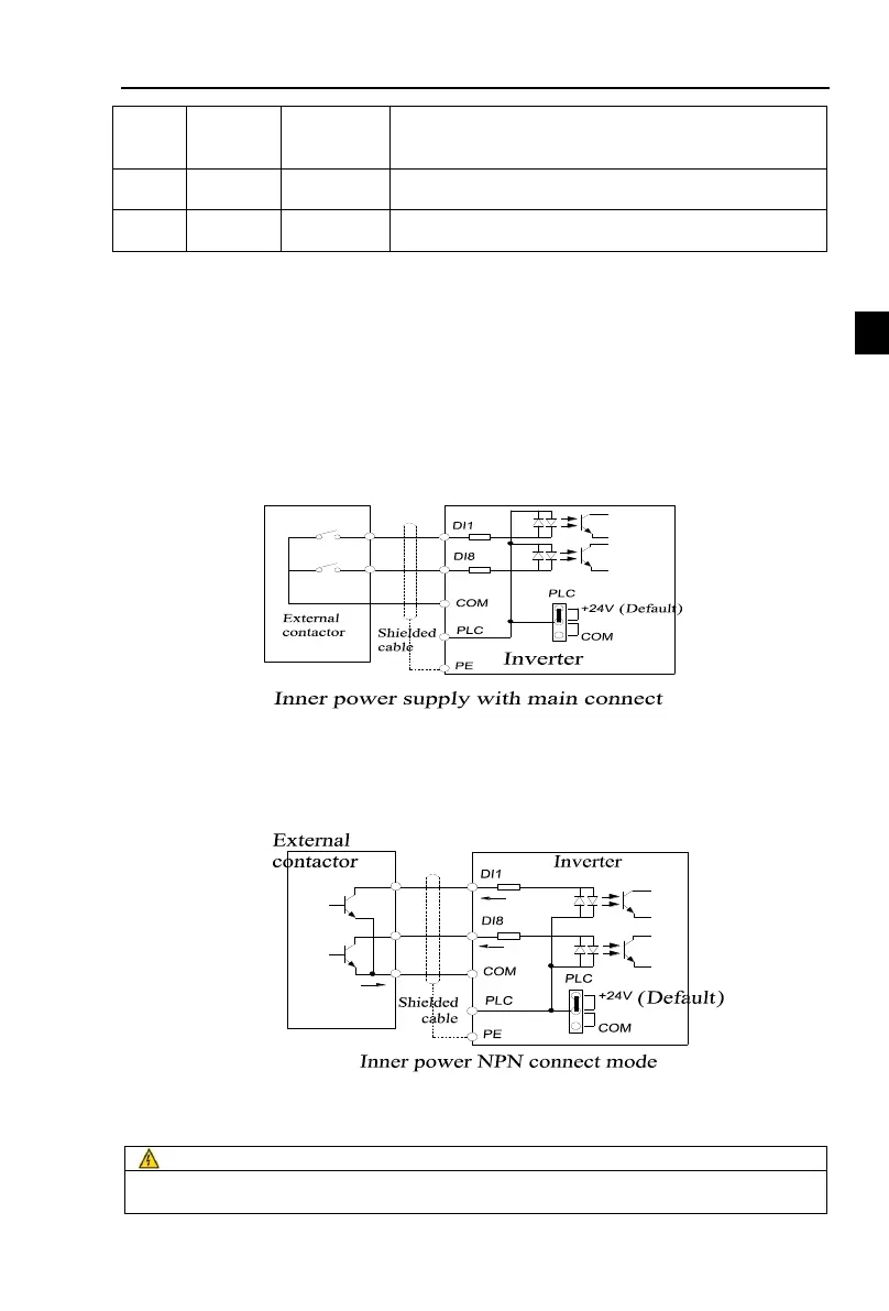
Signal input terminal circuit
Switch input and output signal transmission, generally use the shielded cable and wiring short
distance as far as possible, good grounding and shielding layer on the inverter side, try not to over
20 m transmission distance. Drive in active way, elected to the power of crosstalk necessary
filtering measures are taken, generally recommend that choose dry contact control mode.
Wiring control cable should be kept with the main circuit and high voltage lines (Such as the
power cord, motor connecting line, relay or contactor) more than 20 cm distance, and to avoid high
voltage lines parallel to and can't be avoided and the high voltage lines cross, the proposal USES
vertical wiring way, in order to prevent the misoperation caused by disturbance frequency converter
Dry contact mode:
Figuer 4-15:Signal input terminal circuit- dry contact mode
Open collector NPN connect wire:
When the input signal from the NPN transistor, according to the use of power supply, please
according to the figure + 24 v and PLC jumper cap.
Figuer 4-16:Signal input terminal wiring diagram open collector NPN connection mode
4-5.Wiring Precautions
Make sure that the power switch is in the OFF state before wiring operation, or electrical shock
may occur!

 Loading...
