Chapter 4 Installation and commissioning
20
4-4.Control circuit terminals
4-4-1.Control circuit terminals arrangement
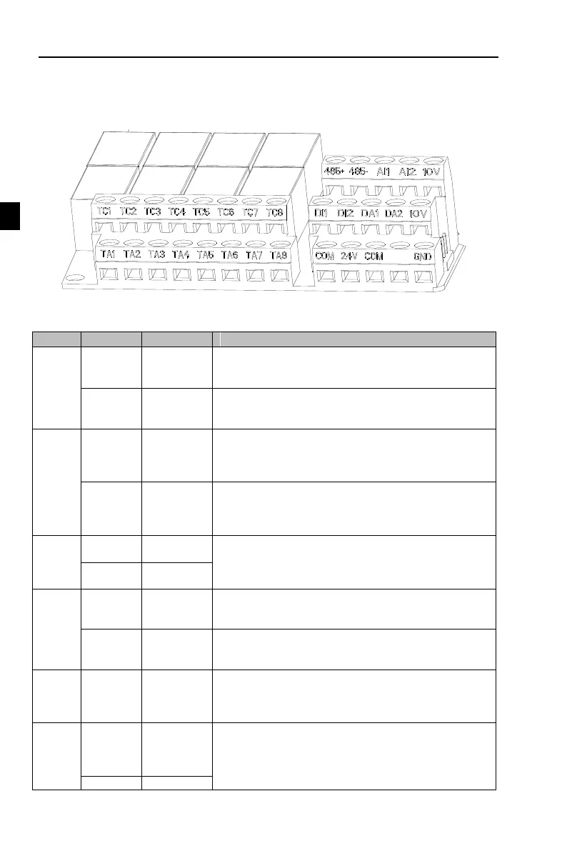
1.Control panel control circuit terminals
Figuer 4-14:Control panel control circuit terminals
4-4-2.Description of control circuit terminals
Output +10V power supply, maximum output current: 10mA
Generally it is used as power supply of external
potentiometer, potentiometer resistance range: 1kΩ to 5kΩ
Output +24V power supply, generally it is used as power
supply of digital input and output terminals and external
sensor.Maximum output current: 200mA
1.Input range:(DC 0V to 10V/0 to 20mA), depends on the
selected AI1 jumper on control panel.
2.Input impedance: 20kΩ with voltage input, 500Ω with
current input.
1.Input range:(DC 0V to 10V/0to 20mA), depends on the
selected AI2 jumper on control panel.
2.Input impedance: 20kΩ with voltage input, 500Ω with
current input.
Multi-function
digital input 1
1.Input impedance: 3.3kΩ
2.Voltage range with level input: 19.2V to 28.8V;
Multi-function
digital input 2
The selected DA1 jumper on control panel determines
voltage or current output. Output voltage range: 0V to
10V , output current range: 0mA to 20mA
The selected DA2 jumper on control panel determines
voltage or current output. Output voltage range: 0V to
10V , output current range: 0mA to 20mA
Normally
open terminals
(TA1-TC1)
to(TA8-TC8)
Contactor drive capacity: contact 5A/AC 250V 1A/DC
30V;COSø=0.4.
485
differential
signal +
terminal
485 communication interface, 485 differential signal
terminal, use twisted-pair or shielded wire connect to the
standard 485 communication interface
485 jump line in the control panel to decide whether to
connect the terminal resistance

 Loading...
