Chapter5.Function parameter
37
SPB terminal is selected as pulse output, the function code is used to select the maximum
value of output pulse.
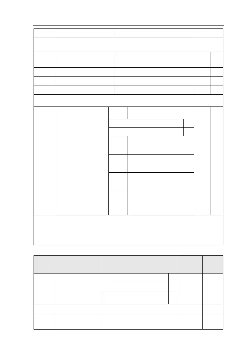
SPB switching quantity
output delay time
Relay 1 output delay time
Relay 2 output delay time
Set the delay time from occurrence to Actual output for output terminal SPA, SPB,
relay 1, relay 2 and expansion DO.
DO output terminal
active status selection
SPB switching quantity
active status selection
Relay 1 terminal active
status setting (0 to 1, as
above)
Expansion D0 terminal
active status setting (0 to 1,
as above)
SPA terminal active status
setting (0 to 1, as above)
Relay 2 terminal active
status setting (0 to 1, as
above)
To define the output logic for output terminal SPA, SPB, relay 1, relay 2 and
expansion DO .0: positive logic:It is active status when the digital output terminal is
connected with the corresponding common terminal, inactive when disconnected; 1: anti-
logic: It is inactive status when the digital output terminal is connected with the
corresponding common terminal, active when disconnected;
5-1-5.F3 Group - Start and stop control group
Pre-excitation start (AC
asynchronous motor)
Hold time for start
frequency

 Loading...
