Chapter8.Installation and Spare Circuit
79
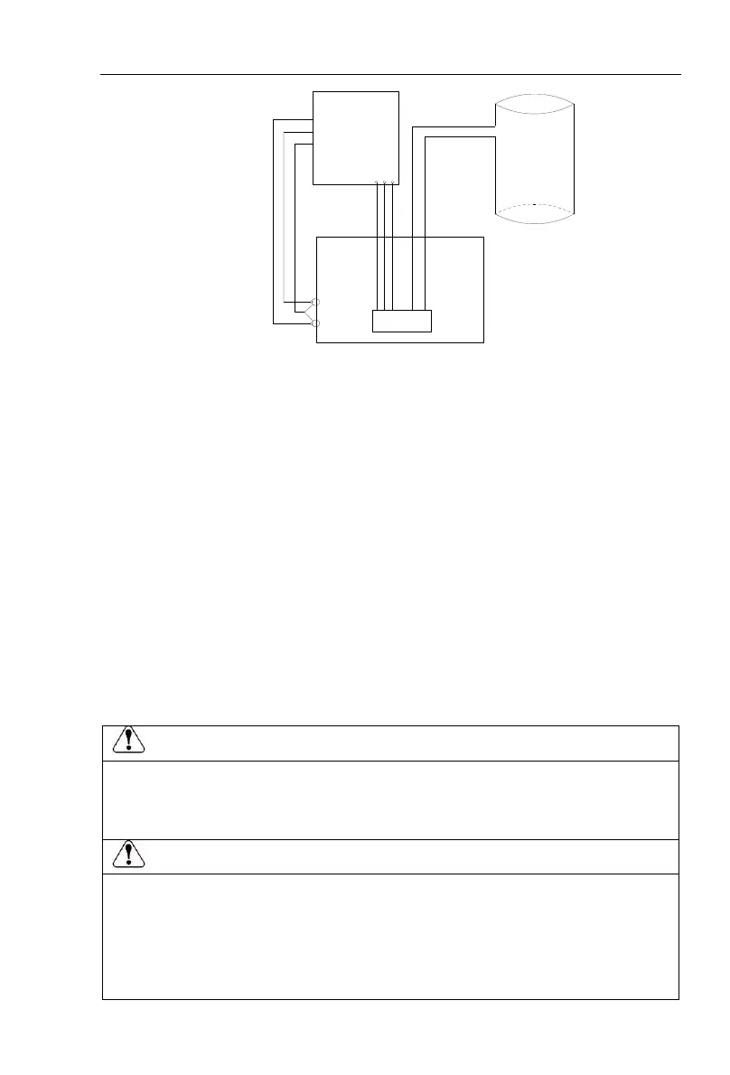
Water
Tower
DI2
DI1
Frequency
inverter
U V
W
Pump
Low level detection
points
Start checkpoint
Well
COM
Parameter settings:
F0.03 = 8 (PV settings);
F0.11 = 4 (keyboard + Terminal + communication);
F1.00 = 1 (forward run);
F1.01 = 8 (freewheel);
F1.10 = 2 (three-wire mode 1);
F1.40 = 1 (input terminal can repeat the definitions);
E3.02 = 3 (three-wire operation control);
E3.05 = 00100;
E0.00 = 2 (MPPT mode)
Mark: If the water tower is set to switch value detection, the well is also set to switch
value detection. Set F1.40 to the input terminal which can be reusable definitions.
Wiring Precautions:
Make sure that the power switch is in the OFF state before wiring operation, or electrical shock may
occur!
Wiring must be performed by a professional trained personnel, or this may cause damage to the
equipment and personal injury!
Must be grounded firmly, otherwise there is a danger of electric shock or fire hazard !
Make sure that the input power is consistent with the rated value of inverter, otherwise which may
cause damage to the inverter!
Make sure that the motor matches the inverter, otherwise which may cause damage to the motor or
activate the inverter protection!
Do not connect power supply to U/T1, V/T2, W/T3 terminals, otherwise which may cause damage to
the inverter!
Do not directly connect braking resistor to DC bus (P), (P +) terminals, otherwise which may cause a
fire!

 Loading...
