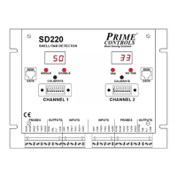
DS600 Non-Ferrous Double Sheet Detector
This document is confidential and proprietary. No part of this document may be disclosed in any manner
to a third party without the prior written consent of Prime Controls, Inc.
202177 8 Revision M
To avoid the REJECT output being latched in the REJECT state, a jumper must be installed
from the RESET terminal to +24V if sourcing I/O is selected or to COM if sinking I/O is selected.
SEL2, SEL1, SEL0, ENABLE
The SEL2-0 and ENABLE terminals are active for the DS600P and DS600PC controllers. These
inputs select between one of eight possible stored calibration memories as described in the
Calibration section (page 11).
2.4.1 IN REF, SEL REF
The IN REF terminal is connected to either common or +24V based on the type of drivers
driving the CAL and RESET inputs. If the drivers are sourcing, then connect IN REF to common.
Conversely, if the drivers are sinking, connect IN REF to +24V. Because IN REF is common to
both CAL and RESET, the driver connected to each must be of the same type.
The SEL REF terminal is connected to either common or +24V based on the type of drivers
driving the SEL0-SEL2 and ENABLE inputs. If the drivers are sourcing, then connect SEL REF
to common. Conversely, if the drivers are sinking, connect SEL REF to +24V. Because SEL
REF is common to SEL0-2 and ENABLE, the driver connected to each must be of the same
type.
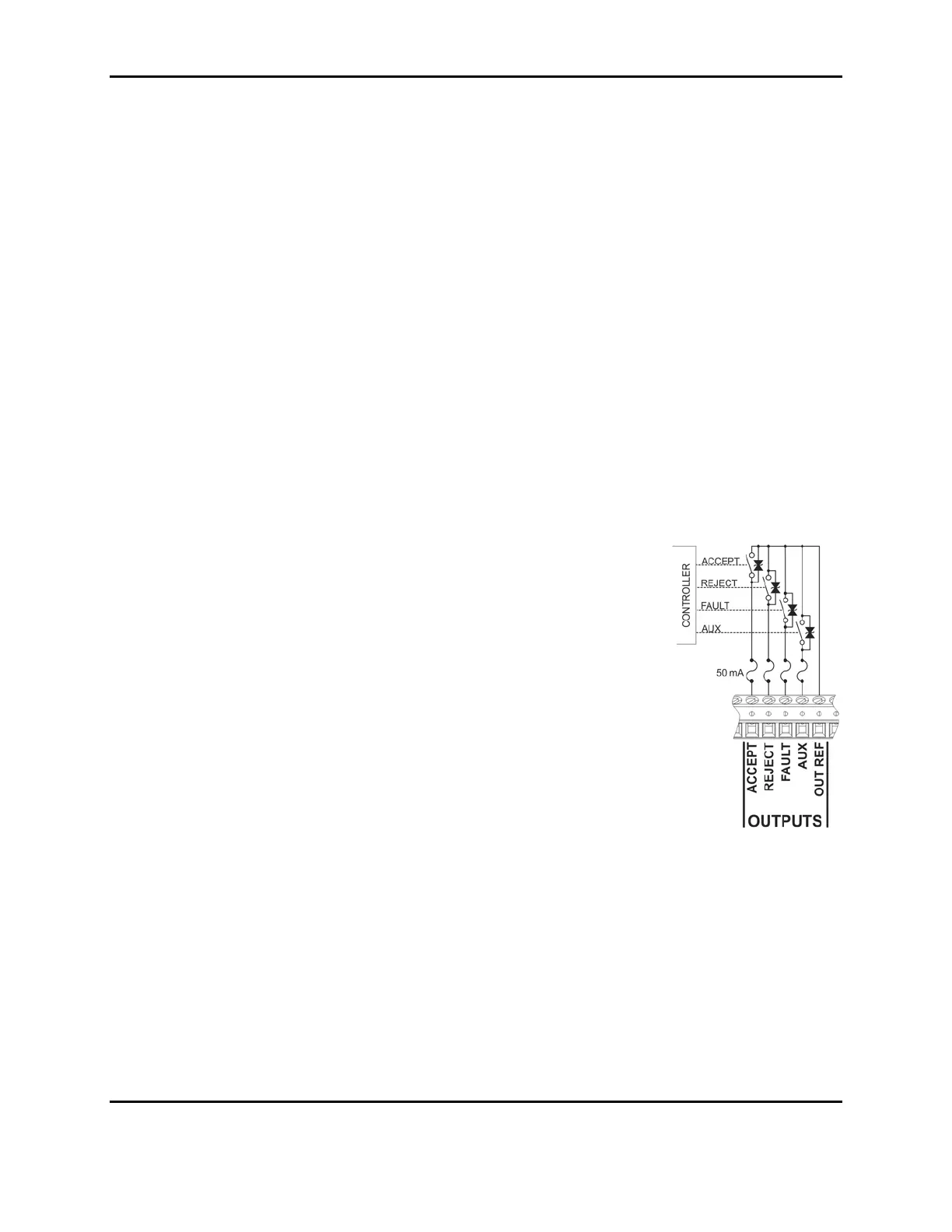
2.5 Output Logic Signals
The controller has four logic outputs for reporting the results of the
gauging operation and the state of the system. The four outputs are
electrically isolated from the internal controller circuitry and the inputs
but share a common reference signal: OUT REF. If the outputs are to
be sinking, connect OUT REF to common. Conversely, if the outputs
are to be sourcing, connect OUT REF to +24V.
Each output is protected from over-voltage by a 30 volt bidirectional
transient suppressor and is fused at 50 milliamps by a self-resetting
fuse.
ACCEPT
This signal is asserted whenever the gauging logic indicates an
acceptable thickness of metal before the probe for double/single
sensing, or the acceptable presence of a part for part present sensing.
See Tables 5-7 for gauging logic outcomes.
REJECT
The logic of the REJECT signal is implemented to provide failsafe operation. This means the
output turns OFF to report a reject condition. Therefore, if the controller loses power, a reject
condition is automatically reported. The REJECT output turns OFF if a double is detected for
single/double sensing or if a part is found to be missing for part present sensing. Optionally, as
determined by the setting of DIP switch 2, a no-metal condition may be reported as a REJECT.
See Tables 5-7 for gauging logic outcomes.
FAULT
Like the REJECT output, the FAULT output is implemented to provide failsafe operation. When
there is no fault to be reported, the output is ON so that a loss of power to or failure of the
controller is more likely to report a fault. The source of faults may be: