DS600 Non-Ferrous Double Sheet Detector
This document is confidential and proprietary. No part of this document may be disclosed in any manner
to a third party without the prior written consent of Prime Controls, Inc.
202177 9 Revision M
• A disconnected probe
• A failed probe
• An internal controller error
AUX
The AUX output is enabled when switch 3 is ON, to report an UNDER condition, namely, a
material condition significantly thinner than the calibrated nominal thickness. Like the REJECT
and FAULT outputs, this signal is implemented to provide failsafe operation; the signal turns
OFF to report an under condition.
2.5.1 OUT REF
The OUT REF terminal is connected to either common or +24V depending upon the type of
output desired for ACCEPT, REJECT, FAULT, and AUX. If sourcing drivers are desired,
connect OUT REF to +24V. Conversely, if sinking drivers are desired, connect OUT REF to
common. Because OUT REF is common to all outputs, all outputs must be the same type.
See Installation (page 4) of this document for further details.
2.6 Modbus Configuration (DS600PC Only)
Prior to using Modbus communication, the unit’s Modbus ID and Modbus Termination DIP
switch (sw8) should be set as required according to the DIP Switch Settings and Changing
Parameter Values sections elsewhere in this document.
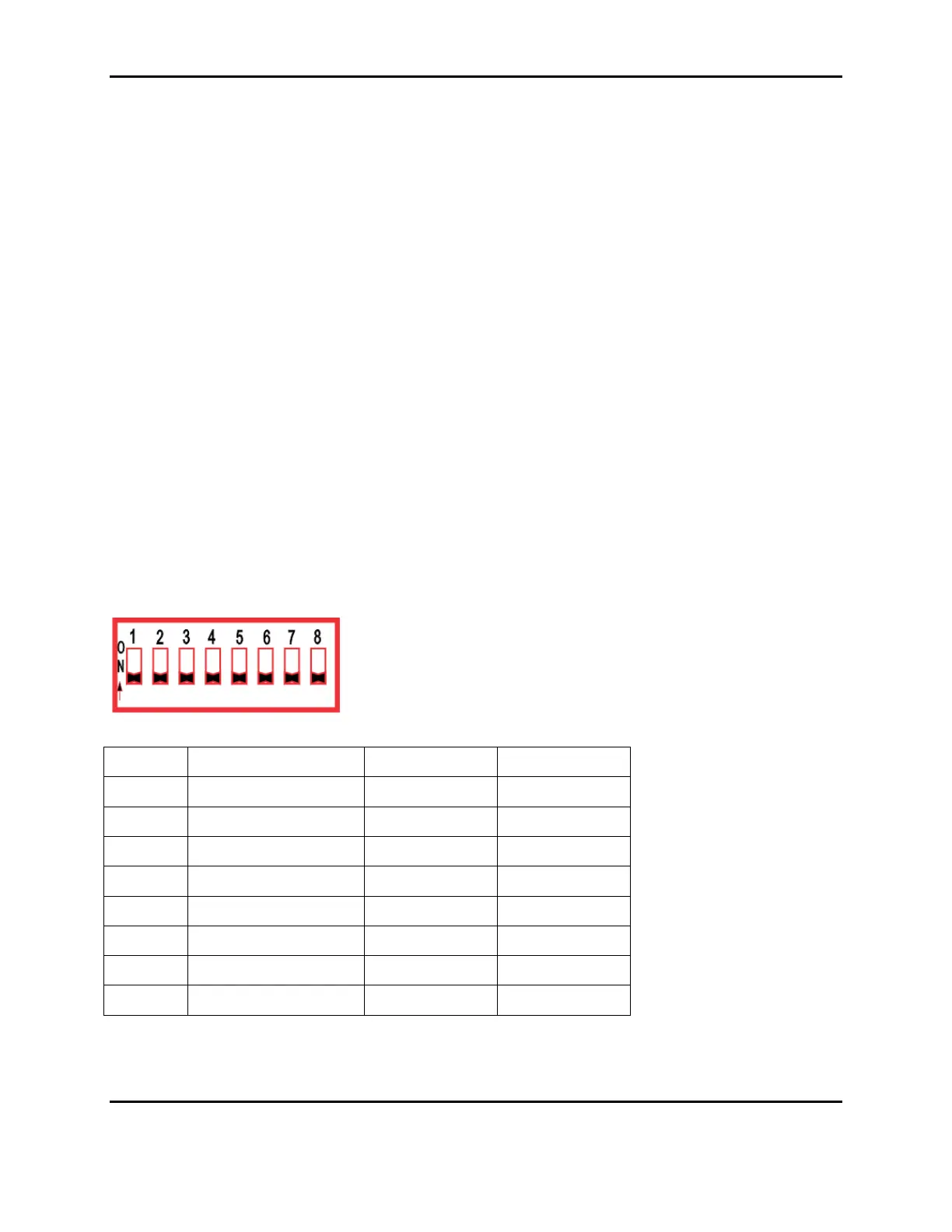
2.7 DIP Switch Settings
Table 2
SWITCH FUNCTION OFF ON
1
Changing the state of this switch will prompt for a recalibration.