1.29
Operation Manual
© 2013 Prism Media Products Ltd
Revision 1.00Prism Sound Lyra
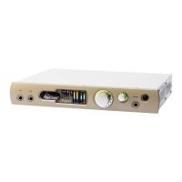
5.3 Front panel
Lyra's front panel contains a limited number of physical controls and indicators. A greater degree of
control is available using the Lyra Control Panel app software provided. The front panel also
contains the instrument input and headphone output jacks.
From left to right:
· Instrument input jacks 1&2: mono unbalanced jacks, high impedance, with finely adjustable gain
control. See Analogue inputs. Note that Lyra 1 has only one instrument input.
· Meter panel: see below.
· Assignable level control: Volume knob which can be assigned to any of Lyra's outputs (except for
the headphone output), as required. This is primarily intended as a monitor volume control for
stereo monitoring. Note that pressing the knob mutes any outputs assigned to the control; this
state is indicated by the LED halo around the knob flashing.
· Headphone jack: with its own volume control.
· Standby button: puts the unit into a low-power standby state. Note that the USB interface is still
active in standby mode, so the Lyra unit can still be recognised by the host, although its inputs and
outputs are inactive. The LED in the standby button flashes to identify the unit in multi-unit setups
when the 'Identify' button in the Control Panel app is clicked. Entering standby mode causes Lyra
to retain its current software control settings in flash, for example for use in stand-alone mode.
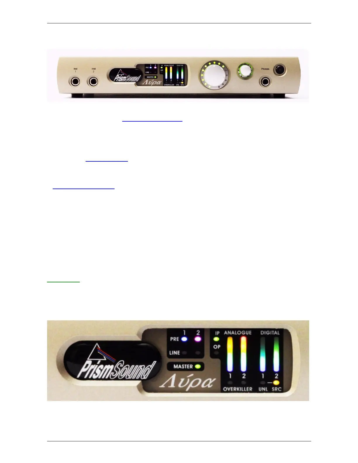
Meter panel
The meter panel contains metering for the analogue input and output channels and the S/PDIF input
and output channels. It also contains the input selection indicators and Overkiller activity indicators
for all the analogue inputs, unlock and SRC indicators for the S/PDIF input, and an SRC indicator for
the S/PDIF output.
From left to right:
· Input selection indicators: these indicators show the analogue input selections; green for line, or