Hardware Modifications
84
Cable Serial Interface
The table shows the technical data of the cable serial interface:
Serial Interface Connections
This interface is used to connect the Slim Panel to remote equipment, via a cable. The connector
is a D-Sub 9-pin plug connector.
By using a long PLC cable to connect to the Slim Panel, it is possible that the cable can be at an
electrical potential that is different from the electrical potential of the panel, even if both are
connected to ground.
The serial port that is not isolated has the signal ground (SG) and the functional ground terminals
connected inside the panel.
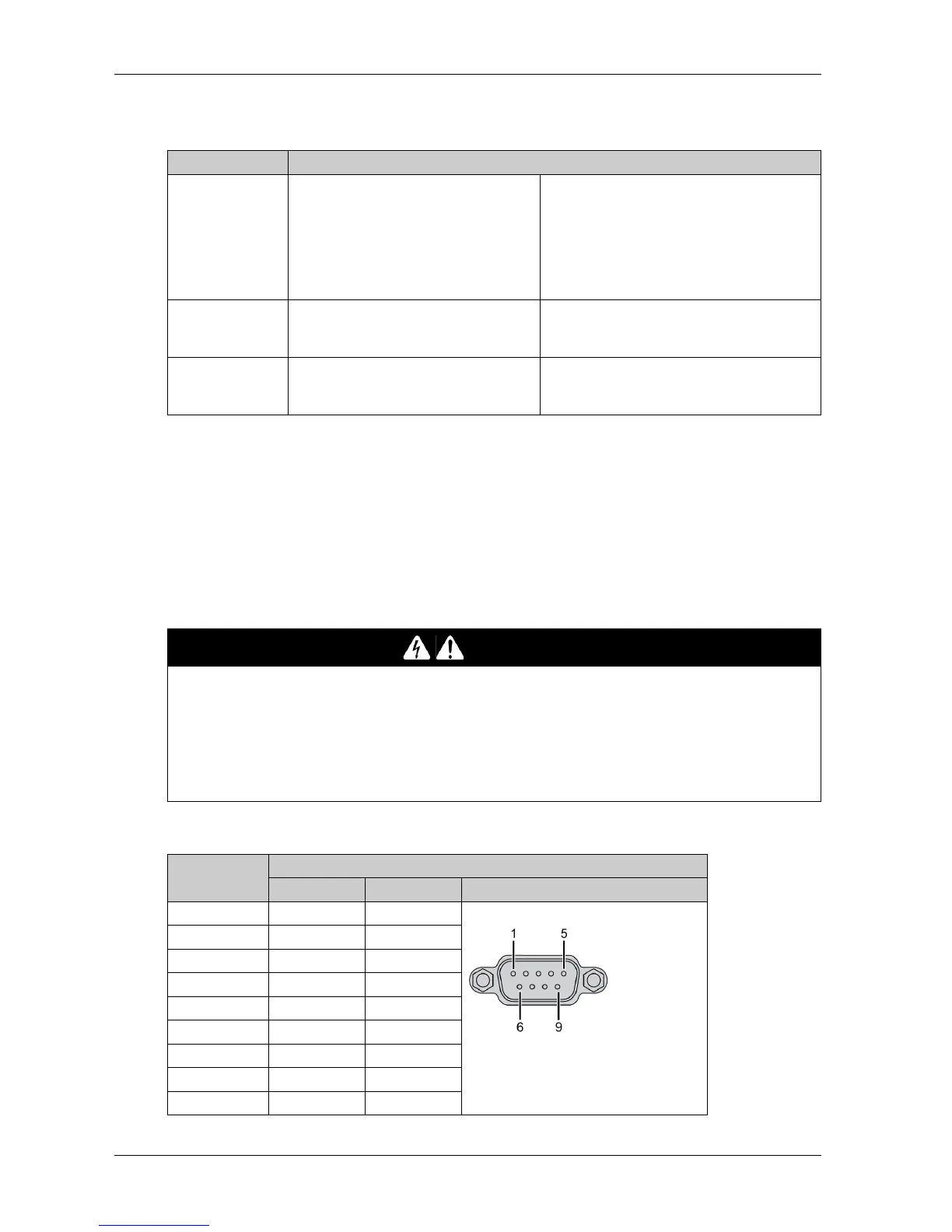
The table shows the D-Sub 9-pin assignments:
Element Characteristics
Signal lines Cable cross section RS-232
Cable cross section RS-422
Cable cross section RS-485
Wire insulation
Conductor resistance
Stranding
Shield
4 x 0.16 mm² (26 AWG), tinned Cu. wire
4 x 0.25 mm² (24 AWG), tinned Cu. wire
4 x 0.25 mm² (24 AWG), tinned Cu. wire
Protective earth ground
≤ 82Ω/km
Wires stranded in pairs
Paired shield with aluminum foil
Grounding line Cable cross section
Wire insulation
Conductor resistance
1 x 0.34 mm² (22 AWG/19), tinned Cu. wire
Protective earth ground
≤ 59Ω/km
Outer sheathing Material
Features
Cable shielding
PUR mixture
Halogen free
From tinned Cu. wires
DANGER
ELECTRIC SHOCK
Make a direct connection between the ground connection screw and ground.
Do not connect other devices to ground through the ground connection screw of this device.
Install all cables according to local codes and requirements. If local codes do not require
grounding, follow a reliable guide such as the US National Electrical Code, Article 800.
Failure to follow these instructions will result in death or serious injury.
Pin Assignment
RS-232 RS-422/485
1 DCD TxD-/Data- D-Sub 9-pin plug connector:
2 RxD TxD+/Data+
3TxDRxD+
4DTRRxD-
5GNDGND/VEE
6 DSR RTS-
7RTSRTS+
8CTSCTS+
9RICTS-