4.3 Preparation
PM200 system is designed with a concept of ‘Plug and Play’ in mind. To complete the easy installation, a screw driver and DC cables are
required. Follow Table 7 recommendation for minimum wiring.
4.4 Connection
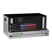
PM200 unit is designed with a spring and screw terminal. Please refer to following illustration at right.
Each type of terminal is designed to fit a different range of cables.
Table 8 Recommended terminal and cable gauge Figure 18 PM235 Terminal
TYPE TERMINAL MODEL
NUMBER
SUITABLE CABLE GAUGE
Type 1 ERTB10-10.16 0.5mm
2
– 10mm
2
Type 2 wago804-114 0.25mm
2
– 2.5mm
2
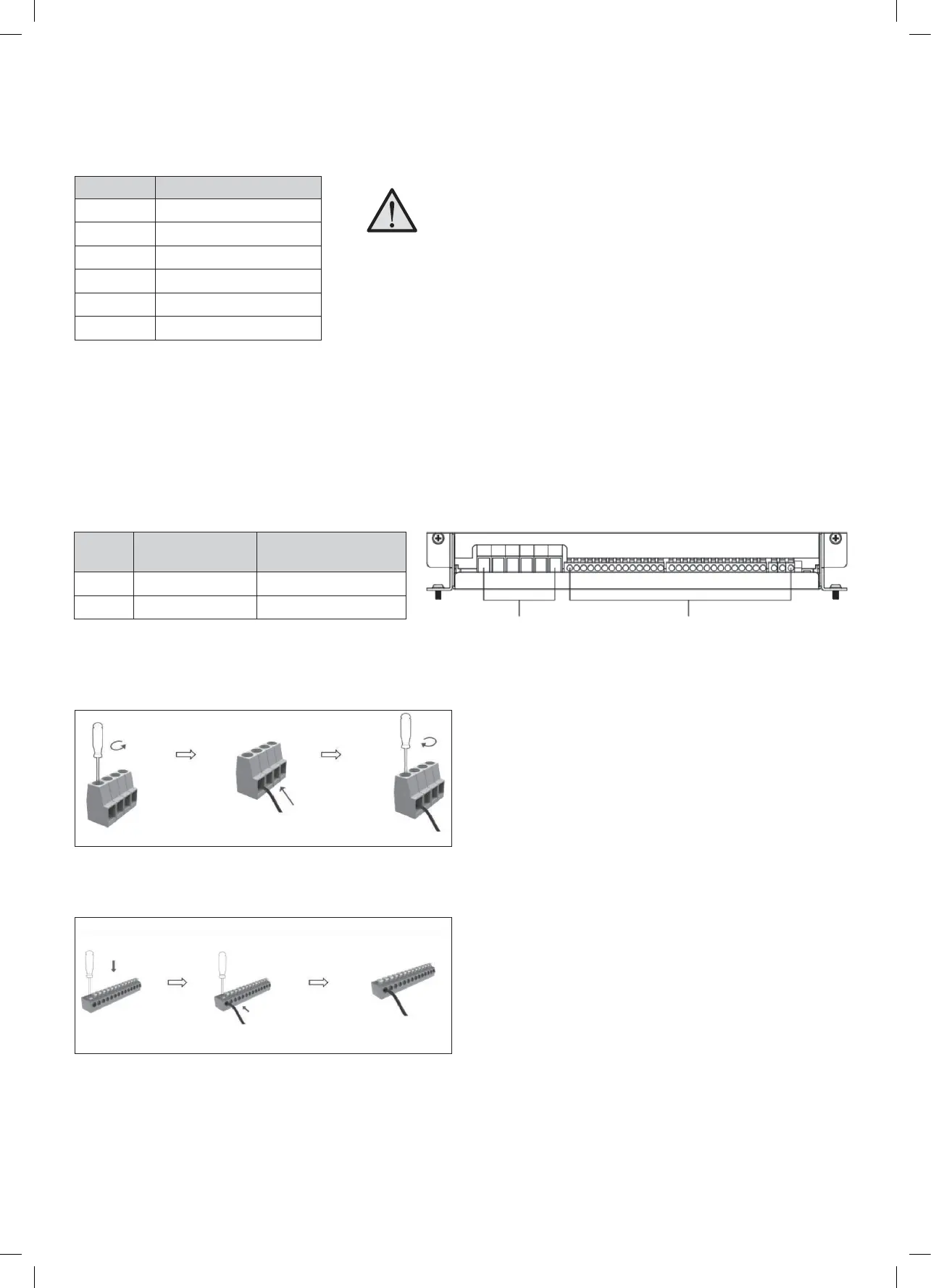
Figure 19 Connection of Terminal Type 1
13
When running cables, if they pass through panels or wall, ensure the
cables are protected from damage by sharp edges. In such cases, it is
recommended to use cable glands.
TYPE 1
TYPE 2
Figure 20 Connection of Terminal Type 2
CURRENT MINIMUM CABLE SIZE
0–5A 1.0mm
2
or 18 AWG
5–10A 2.0mm
2
or 14 AWG
10–15A 3.0mm
2
or 13 AWG
15–20A 4.0mm
2
or 11 AWG
20–25A 5.0mm
2
or 10 AWG
25–30A 6.0mm
2
or 9 AWG
Table 7 Minimum cable size
Type 1 Type 2
 Loading...