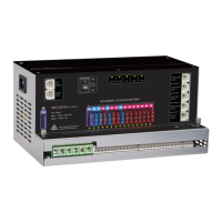
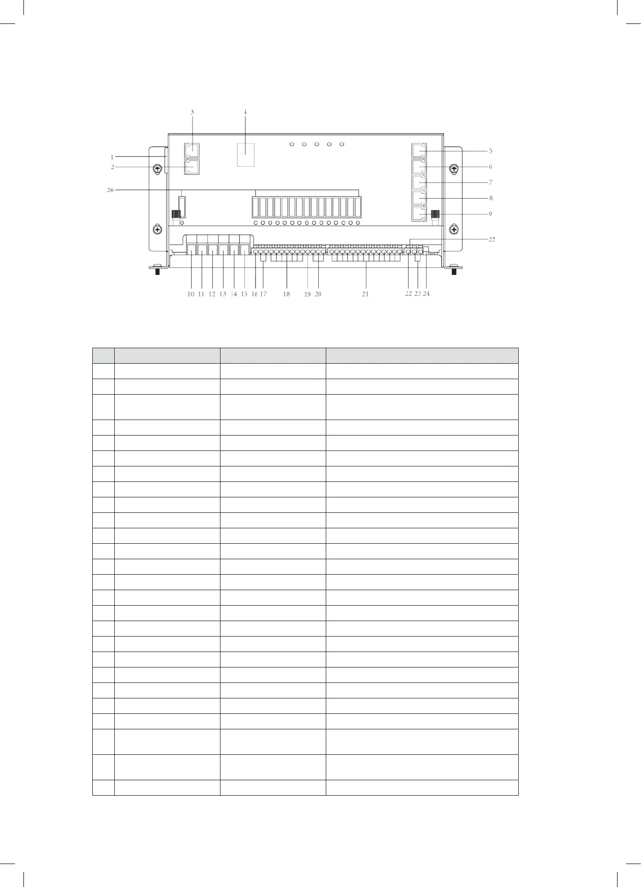
Figure 8 Front panel of PM235
9
Table 5 Connection of PM235
CATEGORY QTY DESCRIPTION POSSIBLE LOAD SUITABLE
Class A1 1 Relay controlled output with fuse, protected by main master switch relay Water pump
Class B 10 Fused outputs, protected by master switch relay Ventilation fan etc
Class C 2 Live load Fridge, security alarm etc.
Class D 1 Permanent on load Auto step
N
O
LABEL DEFINITION DESCRIPTION
1 AC Mains AC input port
2 Switch panel Comm port Connect to switch panel
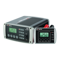
3 LCD Display Comm port Connect to monitor
(Monitor is not available in PM200)
4 Battery switch Service battery switch Manual battery switch
5 Fresh water tank 1 Connect to fresh water tank 1
6 Fresh water tank 2 Fresh water tank 2 is not available in PM200
7 Tap water tank Connect to tap water tank
8 Waste water tank Connect to waste water tank
9 Battery sensor For temp compensation Connect to service battery+
10 PV+ Solar input Connect to PV+
11 PV- Solar input Connect to PV-
12 Starter Bat+ Starter battery+ Connect to starter battery+
13 Service Bat+ Service battery+ Connect to service battery+
14 Starter Bat- Starter battery- Connect to starter battery-
15 Service Bat- Service battery- Connect to service battery-
16 L1+ Step Connect to load of class D
17 L2+ ~ L3+ Connect to load of class C
18 L4+ ~ L10+ Connect to load of class B
19 L11+ Water pump Connect to Water pump+
20 L12+ ~ L14+ Connect to load of class B
21 L1- ~ L14- Connect to DC load -
22 D+ Point D+ input Connect to D+
23 Remote Switch Terminal block Connect to remote switch
24 Select Switch Dip switch Select local switch or remote switch
(Note: open the upper cover board to operate)
25 Setting Dip switch Set the battery type and capacity
(Note: open the upper cover board to operate)
26 Fuse Fuses and fuse failure indication
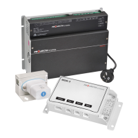
3. STRUCTURE AND INSTALLATION
3.1 PM200 Master Power Unit
 Loading...