FM15_P28 HV PN7 (-TS) Ver I_052217
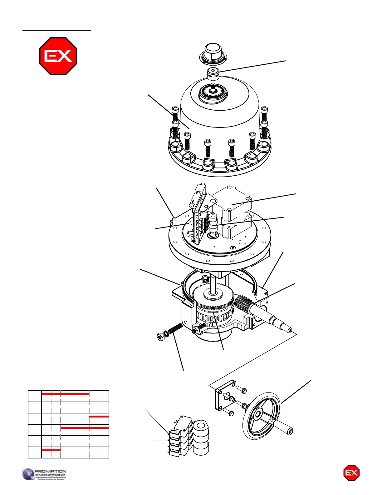
P Series Exploded View
(P2/3-120N7 unit is shown)
Easily distinguishable
yellow/red position
indicator
Worm Drive
Heavy Duty
Drive Motor
Easily accessible
switch & cam stacks
Modular
Control
Cards
Alignment
Pins (2)
Clutchless
Override
Handwheel
Aluminum Casting,
Class 1 / Div 1
Class 2 / Div 1
Protection
Aluminum Casting
Cover Seal
Epicyclic Gearing
Mechanical Stop
Screws (2)
Switch sequencing data is provided in the
table below to show the change-of-state
points during the rotation of the actuator
from CCW to CW and back again. The
red bars indicate when that terminal
makes with it’s respective common.
Limit switches for SW1 and SW2 are
set at the factory and should NOT be
changed. The INCLUDED auxiliary
switches SW3 & SW4 are for terminals
7 thru 12 and those set points may
be modified if need be. When so
optioned, SW5 & SW6 auxiliary switches
are initially set to function the same
as auxiliary switches SW3 & SW4.
Switch Logic Map
and Switch/Cam
Arrangement
Terminal ID#
12
11
10
9
8
7
-5
°
0
°
CW CCW
85
°
5
°
90
°
95
°
SW3 CCW AUX
(Factory Set - Adj)
SW4 CW AUX
(Factory Set - Adj)
}
}
Closed Common
Open Common
}
Used by
Controller
Open
Not Closed
Closed
Not Open
Page 17 P2/3 HV-PN7 Series
Terminal ID#
12
11
10
9
8
7
-5
°
0
°
CW CCW
85
°
5
°
90
°
95
°
SW3 CCW AUX
(Factory Set - Adj)
SW4 CW AUX
(Factory Set - Adj)
}
}
Closed Common
Open Common
}
Used by
Controller
Open
Not Closed
Closed
Not Open
Mechanical Data