FM15_P28 HV PN7 (-TS) Ver I_052217
1. Fully CLOSE the valve or damper to which the actuator is to be mounted.
• Keep in mind this actuator rotates CW (as viewed from above the unit) when driving CLOSED.
2. Assemble necessary linkage components and attach the actuator to the driven device.
3. Tighten mounting bolts, making sure actuator is centered on the device drive shaft.
4. Utilize the handwheel to check for unobstructed manual operation from fully CCW to fully CW positions BEFORE
applying power to the unit.
5. Make the electrical connections per wiring diagram on page 5.
• Connect POWER to terminals marked 1 and 2.
• Actuator accepts a 4-20mA (default), 0-10VDC, 1-5VDC, or 2-10VDC signal.
• Connect CONTROL wires on the control card (430-10102) to terminals marked ANALOG: IN and COM. The
positive wire MUST connect to IN or the controller will not function.
• Wires may be connected on the control card (430-10102) to ANALOG: Out and COM for remote position sensing.
• Terminals 7-12 on the switch card (430-10100) are for the (adjustable) aux switches. They are dry type Form C
rated 10A @ 250vac MAX.
• The drain wire on the signal cables must be grounded at ONE END ONLY! (Preferably at the supply end).
6. Do NOT apply power at this time.
• These actuators are designed to be used between a horizontal and upright position. Do NOT mount the assembly with
the actuator top below a horizontal position.
• When installing conduit, use proper techniques for entry into the actuator. Use drip loops to prevent conduit condensate
from entering the actuator.
• Mechanical travel stops are factory calibrated for 90 degree operation. These stops are NOT designed to adjust
mechanical rotation by more than +/- 3 degrees, they are for positioning the handwheel only.
• Both NPT conduit ports MUST use proper equipment to protect the rated integrity of the housing.
• The internal heater is to be used in ALL applications.
• Do NOT install the actuator outdoors or in humid environments unless it is powered up and the heater is functioning.
• Use proper wire size to prevent actuator failure (see chart on page 5).
• All terminals accept 12-16AWG solid/stranded wire.
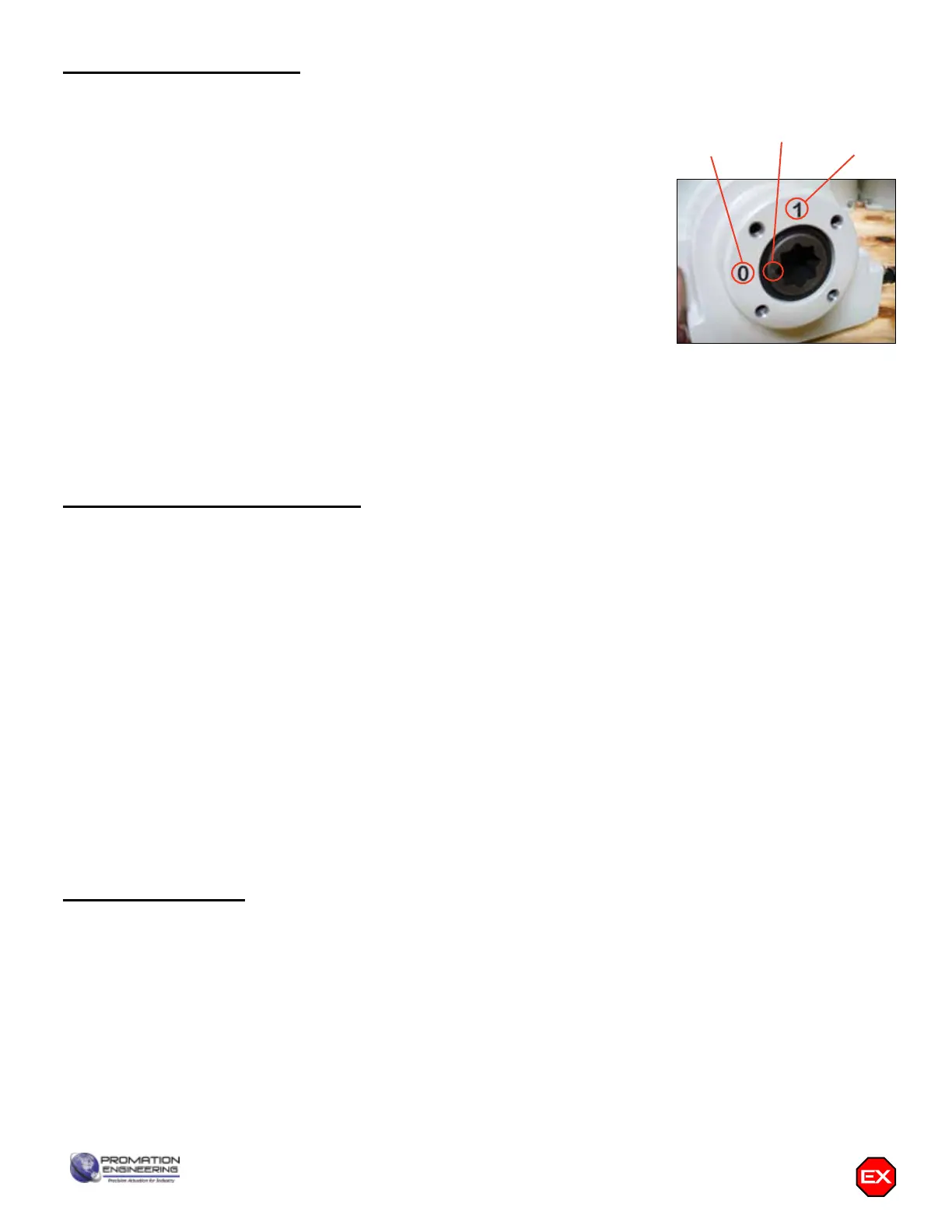
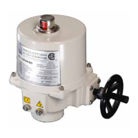
1. This actuator is shipped in the FULLY CW position (2 color position indicator shows
“CLOSE” and the Reference Dimple aligns with “0”). (The “1” mark is the FULLY
CCW position).
2. CONDUIT DEVICES MUST COMPLY WITH ALL APPLICABLE ELECTRICAL
CODES FOR HAZARDOUS LOCATIONS.
LES DISPOSITIFS DE CONDUIT DOIVENT ÊTRE CONFORMÉS
DE TOUS LES CODES ÉLECTRIQUES APPLICABLES POUR
LOCATIONS DANGEREUSES.
3. Storage: This unit should NOT be stored outside unless it is powered up and
has proper conduit terminations. When NOT powered up, it should be stored
in a clean, dry environment at all times.
4. This actuator has been factory calibrated to operate between 0 degrees and
90 degrees. Most quarter-turn products will not require recalibration of these
settings. Check alignment of actuator and driven device. If any travel adjustment
is necessary, please refer to pages 8-14 for instructions.
5. The actuator CANNOT operate with a rotation greater than 95 degrees without changing mechanical stops.
Page 4 P2/3 HV-PN7 Series
“1” = CCW
“0” = CW
REFERENCE
DIMPLE
0 and 1 colored for clarity
Shipping and Handling
Product Mounting and Setup
Installation Notes