FM15_P28 HV PN7 (-TS) Ver I_052217
Page 7 P2/3 HV-PN7 Series
The proportional control card has been calibrated and tested at the factory to operate between
0 degrees and 90 degrees operating range. There is normally no need for any adjustments at
this point in the installation. Changes from the factory set cam settings and controller settings
can be very dif cult to reverse.
The default settings in the controller are as follows:
• Input/OutputSignal: 4-20mA(unlessotherwisespecifiedattimeofFactoryorder)
• Signal Response: Direct Acting (max signal = CCW)
• Loss of Signal: Fail in Position
• Controller version: 1.15
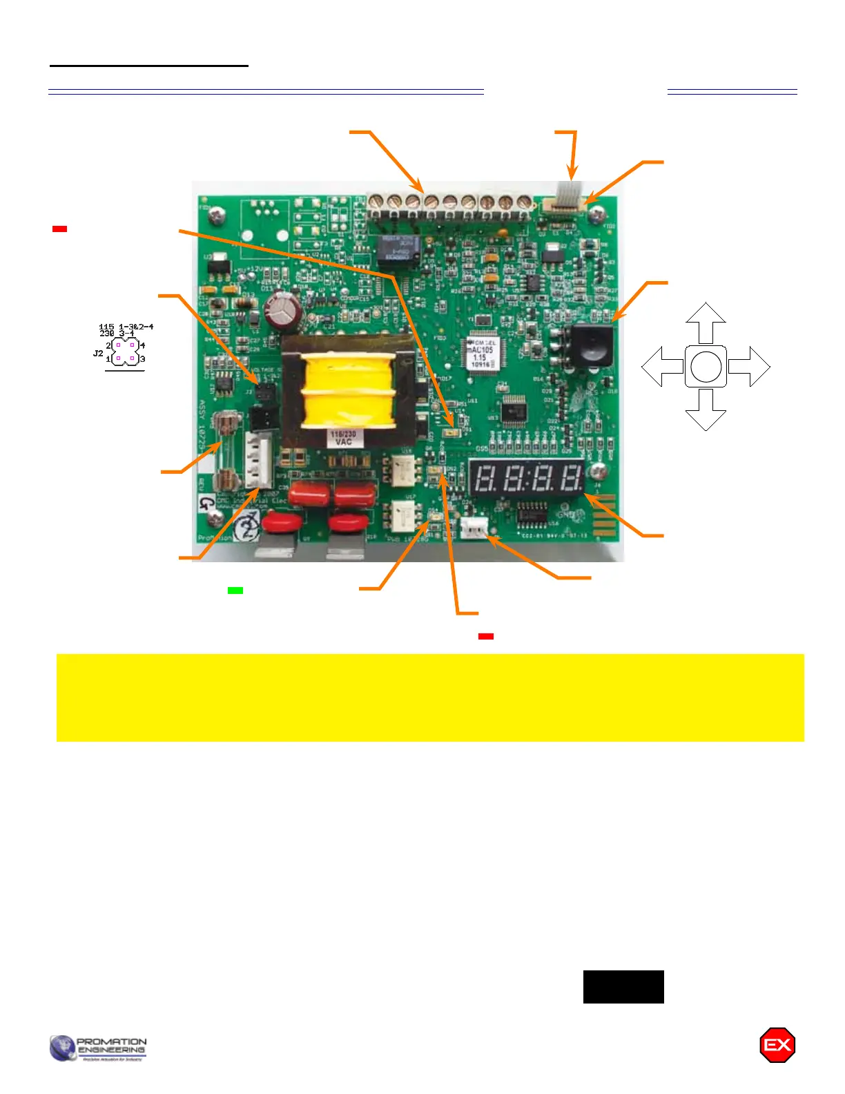
The Fault Status indicator will blink once per second under normal operating conditions. It will blink approximately three
times per second if a fault has occurred. A fault status indication will not return to normal unless the fault has been cleared
or the board has been powered down.
Under normal operation, the 4 digit display will show percentage of CCW position...i.e. 25 = 25% CCW, or roughly 22
degrees CCW.
Proportional Control
Thermal Sensor
Ribbon Cable
Thermal Sensor
Connector
Joystick
Signal Connections
Fault Status
(red LED)
5A Fuse
Switch Card
Connector
Potentiometer
Connector
4 Digit Display
Driving CCW
(green LED)
Driving CCW
(red LED)
p
u
L
p
u
R
Joystick
Signal Connection
4 digit display
5A Fuse
Driving Open
Driving Closed
Fault Status
Voltage Sel
Thermal Sensor Connector
Potentiometer Connector
GRN
RED
RED
Switch Card Connector
Joystick Functionality
825.0
Voltage
Select
p
u
L
p
u
R
Joystick
Signal Connection
4 digit display
5A Fuse
Driving Open
Driving Closed
Fault Status
Voltage Sel
Thermal Sensor Connector
Potentiometer Connector
GRN
RED
RED
Switch Card Connector
Voltage Select
Settings
Diagram of Controller